The App Delivery Fabric with Secure Multicloud Networking
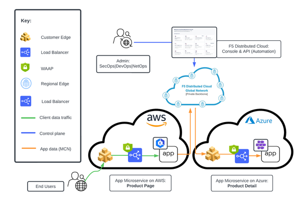
This tutorial with accompanying workflow guide deploys customer edge sites and uses Distributed Cloud Multicloud Networking App Connect to establish a Secure MCN App Delivery Fabric, enabling only Layer7 app connectivity between two cloud sites. Manual and automation workflows show how to make this NetOps and DevOps task come to life.142Views1like0CommentsUsing Distributed Application Security Policies in Secure Multicloud Networking Customer Edge Sites
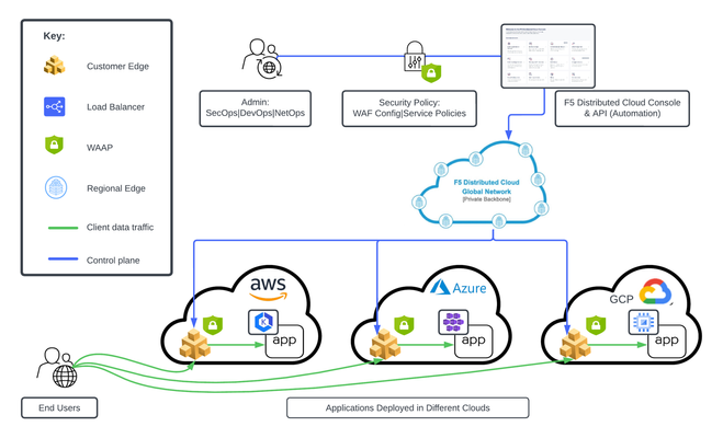
This tutorial and workflow guide deploys and uses F5 Distributed Cloud App Security policies with apps at local customer edge sites. Deploy a policy in any customer edge site regardless of location in the cloud or on-prem. Manual and automation workflows show how to make this NetOps and DevOps friendly solution come to life.206Views0likes0CommentsHow I did it - "Securing Nvidia Triton Inference Server with NGINX Plus Ingress Controller”
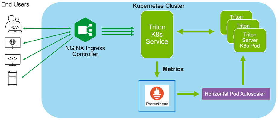
In this installment of "How I Dit it", we step into the world of AI and Machine learning (ML) and take a look at how F5’s NGINX Plus Ingress Controller can provide secure and scalable external access to Nvidia’s Triton Inference Servers hosted on Kubernetes.123Views0likes0CommentsScalable AI Deployment: Harnessing OpenVINO and NGINX Plus for Efficient Inference
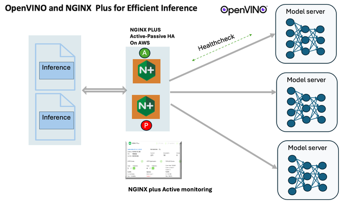
Introduction In the realm of artificial intelligence (AI) and machine learning (ML), the need for scalable and efficient AI inference solutions is paramount. As organizations deploy increasingly complex AI models to solve real-world problems, ensuring that these models can handle high volumes of inference requests becomes critical. NGINX Plus serves as a powerful ally in managing incoming traffic efficiently. As a high-performance web server and reverse proxy server, NGINX Plus is adept at load balancing and routing incoming HTTP and TCP traffic across multiple instances of AI model serving environments. The OpenVINO Model Server, powered by Intel's OpenVINO toolkit, is a versatile inference server supporting various deep learning frameworks and hardware acceleration technologies. It allows developers to deploy and serve AI models efficiently, optimizing performance and resource utilization. When combined with NGINX Plus capabilities, developers can create resilient and scalable AI inference solutions capable of handling high loads and ensuring high availability. Health checks allow NGINX Plus to continuously monitor the health of the upstream OVMS instances. If an OVMS instance becomes unhealthy or unresponsive, NGINX Plus can automatically route traffic away from it, ensuring that inference requests are processed only by healthy OVMS instances. Health checks provide real-time insights into the health status of OVMS instances. Administrators can monitor key metrics such as response time, error rate, and availability, allowing them to identify and address issues proactively before they impact service performance. In this article, we'll delve into the symbiotic relationship between the OpenVINO Model Server, and NGINX Plus to construct a robust and scalable AI inference solution. We'll explore setting up the environment, configuring the model server, harnessing NGINX Plus for load balancing, and conducting testing. By the end, readers will gain insights into how to leverage Docker, the OpenVINO Model Server, and NGINX Plus to build scalable AI inference systems tailored to their specific needs. Flow explanation: Now, let's walk through the flow of a typical inference request. When a user submits an image of a zebra for inference, the request first hits the NGINX load balancer. The load balancer then forwards the request to one of the available OpenVINO Model Server containers, distributing the workload evenly across multiple containers. The selected container processes the image using the optimized deep-learning model and returns the inference results to the user. In this case, the object is named zebra. OpenVINO™ Model Server is a scalable, high-performance solution for serving machine learning models optimized for Intel® architectures. The server provides an inference service via gRPC, REST API, or C API -- making it easy to deploy new algorithms and AI experiments. You can visit https://hub.docker.com/u/openvino for reference. Setting up: We'll begin by deploying model servers within containers. For this use case, I'm deploying the model server on a virtual machine (VM). Let's outline the steps to accomplish this: Get the docker image for OpenVINO ONNX run time docker pull openvino/onnxruntime_ep_ubuntu20 You can also visit https://docs.openvino.ai/nightly/ovms_docs_deploying_server.html for OpenVINO model server deployment in a container environment. Begin by creating a docker-compose file following the structure below: https://raw.githubusercontent.com/f5businessdevelopment/F5openVino/main/docker-compose.yml version: '3' services: resnet1: image: openvino/model_server:latest command: > --model_name=resnet --model_path=/models/resnet50 --layout=NHWC:NCHW --port=9001 volumes: - ./models:/models ports: - "9001:9001" resnet2: image: openvino/model_server:latest command: > --model_name=resnet --model_path=/models/resnet50 --layout=NHWC:NCHW --port=9002 volumes: - ./models:/models ports: - "9002:9002" # Add more services for additional containers if needed Make sure you have Docker and Docker Compose installed on your system. Place your model files in the `./models/resnet50` directory on your local machine. Save the provided Docker Compose configuration to a file named `docker-compose.yml`. Run the following command in the directory containing the `docker-compose.yml` file to start the services: docker-compose up -d You can now access the OpenVINO Model Server instances using the specified ports (e.g., `http://localhost:9001` for `resnet1` and `http://localhost:9002` for `resnet2`). - Ensure that the model files are correctly placed in the `./models/resnet50` directory before starting the services. Set up an NGINX Plus proxy server. You can refer to https://docs.nginx.com/nginx/admin-guide/installing-nginx/installing-nginx-plus/ for NGINX Plus installation also You have the option to configure VMs with NGINX Plus on AWS by either: Utilizing the link provided below, which guides you through setting up NGINX Plus on AWS via the AWS Marketplace: NGINX Plus on AWS Marketplace or Following the instructions available on GitHub at the provided repository link. This repository facilitates spinning up VMs using Terraform on AWS and deploying VMs with NGINX Plus under the GitHub repository - F5 OpenVINO The NGINX Plus proxy server functions as a proxy for upstream model servers. Within the upstream block, backend servers (model_servers) are defined along with their respective IP addresses and ports. In the server block, NGINX listens on port 80 to handle incoming HTTP/2 requests targeting the specified server name or IP address. Requests directed to the root location (/) are then forwarded to the upstream model servers utilizing the gRPC protocol. The proxy_set_header directives are employed to maintain client information integrity while passing requests to the backend servers. Ensure to adjust the IP addresses, ports, and server names according to your specific setup. Here is an example configuration is also available at Github Link upstream model_servers { server 172.17.0.1:9001; server 172.17.0.1:9002; server 172.17.0.1:9003; server 172.17.0.1:9004; server 172.17.0.1:9005; server 172.17.0.1:9006; server 172.17.0.1:9007; server 172.17.0.1:9008; zone model_servers 64k; } server { listen 80 http2; server_name 10.0.0.19; # Replace with your domain or public IP location / { grpc_pass grpc://model_servers; health_check type=grpc grpc_status=12; # 12=unimplemented proxy_set_header Host $host; proxy_set_header X-Real-IP $remote_addr; proxy_set_header X-Forwarded-For $proxy_add_x_forwarded_for; } } If you are using gRPC with SSL please refer to the detailed configuration at NGINX Plus SSL Configuration Here is the explanation: upstream model_servers { server 172.17.0.1:9001; # Docker bridge network IP and port for your container server 172.17.0.1:9002; # Docker bridge network IP and port for your container .... .... } This section defines an upstream block named model_servers, which represents a group of backend servers. In this case, there are two backend servers defined, each with its IP address and port. These servers are typically the endpoints that NGINX will proxy requests to. server { listen 80 http2; server_name 10.1.1.7; # Replace with your domain or public IP This part starts with the main server block. It specifies that NGINX should listen for incoming connections on port 80 using the HTTP/2 protocol (http2), and it binds the server to the IP address 10.1.1.7. Replace this IP address with your domain name or public IP address. location / { grpc_pass grpc://model_servers; health_check type=grpc grpc_status=12; # 12=unimplemented proxy_set_header Host $host; proxy_set_header X-Real-IP $remote_addr; proxy_set_header X-Forwarded-For $proxy_add_x_forwarded_for; } Within the location/block, NGINX defines how to handle requests to the root location. In this case, it's using gRPC (grpc_pass grpc://model_servers;) to pass the requests to the upstream servers defined in the model_servers block. The proxy_set_header directives are used to set headers that preserve client information when passing requests to the backend servers. These headers include Host, X-Real-IP, and X-Forwarded-For. Health checks with type=grpc enable granular monitoring of individual gRPC services and endpoints. You can verify the health of specific gRPC methods or functionalities, ensuring each service component is functioning correctly. In summary, this NGINX configuration sets up a reverse proxy server that listens for HTTP/2 requests on port 80 and forwards them to backend servers (model_servers) using the gRPC protocol. It's commonly used for load balancing or routing requests to multiple backend servers. Inference Testing: This is how you can conduct testing. On the client side, we utilize a script named predict.py. Below is the script for reference # Import necessary libraries import numpy as np from classes import imagenet_classes from ovmsclient import make_grpc_client # Create a gRPC client to communicate with the server # Replace "10.1.1.7:80" with the IP address and port of your server client = make_grpc_client("10.1.1.7:80") # Open the image file "zebra.jpeg" in binary read mode with open("zebra.jpeg", "rb") as f: img = f.read() # Send the image data to the server for prediction using the "resnet" model output = client.predict({"0": img}, "resnet") # Extract the index of the predicted class with the highest probability result_index = np.argmax(output[0]) # Print the predicted class label using the imagenet_classes dictionary print(imagenet_classes[result_index]) This script imports necessary libraries, establishes a connection to the server at the specified IP address and port, reads an image file named "zebra.jpeg," sends the image data to the server for prediction using the "resnet" model, retrieves the predicted class index with the highest probability, and prints the corresponding class label. Results: Execute the following command from the client machine. Here, we are transmitting this image of Zebra to the model server. python3 predict.py zebra.jpg #run the Inference traffic zebra. The prediction output is 'zebra'. Let's now examine the NGINX Plus logs cat /var/log/nginx/access.log 10.1.1.7 - - [13/Apr/2024:00:18:52 +0000] "POST /tensorflow.serving.PredictionService/Predict HTTP/2.0" 200 4033 "-" "grpc-python/1.62.1 grpc-c/39.0.0 (linux; chttp2)" This log entry shows that a POST request was made to the NGINX server at the specified timestamp, and the server responded with a success status code (200). The request was made using gRPC, as indicated by the user agent string. Conclusion: Using NGINX Plus, organizations can achieve a scalable and efficient AI inference solution. NGINX Plus can address disruptions caused by connection timeouts/errors, sudden spikes in request rates, or changes in network topology. OpenVINO Model Server optimizes model performance and inference speed, utilizing Intel hardware acceleration for enhanced efficiency. NGINX Plus acts as a high-performance load balancer, distributing incoming requests across multiple model server instances for improved scalability and reliability. Together, this enables seamless scaling of AI inference workloads, ensuring optimal performance and resource utilization. You can look at this video for reference: https://youtu.be/Sd99woO9FmQ References: https://hub.docker.com/u/openvino https://docs.nginx.com/nginx/deployment-guides/amazon-web-services/high-availability-keepalived/ https://www.nginx.com/blog/nginx-1-13-10-grpc/ https://github.com/f5businessdevelopment/F5openVino.git https://docs.openvino.ai/nightly/ovms_docs_deploying_server.html236Views0likes0CommentsHow To Run Ollama On F5 AppStack With An NVIDIA GPU In AWS
If you're just getting started with AI, you'll want to watch this one, as Michael Coleman shows Aubrey King, from DevCentral, how to run Ollama on F5 AppStack on an AWS instance with an NVIDIA Tesla T4 GPU. You'll get to see the install, what it looks like when a WAF finds a suspicious conversation and even a quick peek at how Mistral handles a challenge differently than Gemma. 35Views2likes0Comments
Using Distributed Cloud DNS Load Balancer with Geo-Proximity and failover scenarios
Introduction To have both high performance and responsive apps available on the Internet, you need a cloud DNS that’s both scalable and one that operates at a global level to effectively connect users to the nearest point of presence. The F5 Distributed Cloud DNS Load Balancer positions the best features used with GSLB DNS to enable the delivery of hybrid and multi-cloud applications with compute positioned right at the edge, closest to users. With Global Server Load Balancing (GSLB) features available in a cloud-based SaaS format, the Distributed Cloud DNS Load Balancer has a number distinct advantages: Speed and simplicity: Integrate with DevOps pipelines, with an automation focus and a rich and intuitive user interface Flexibility and scale: Global auto-scale keeps up with demand as the number of apps increases and traffic patterns change Security: Built-in DDoS protection, automatic failover, and DNSSEC features help ensure your apps are effectively protected. Disaster recovery: With automatic detection of site failures, apps dynamically fail over to individual recovery-designated locations without intervention. Adding user-location proximity policies to DNS load balancing rules allows the steering of users to specific instances of an app. This not only improves the overall experience but it guarantees and safeguards data, effectively silo’ing user data keeping it region-specific. In the case of disaster recovery, catch-all rules can be created to send users to alternate destinations where restrictions to data don’t apply. Integrated Solution This solution uses a cloud-based Distributed Cloud DNS to load balance traffic to VIP’s that connect to region-specific pools of servers. When data privacy isn’t a requirement, catch-all rules can further distribute traffic should a preferred pool of origin servers become unhealthy or unreachable. The following solution covers the following three DNS LB scenarios: Geo-IP Proximity Active/Standby failover within a region Disaster Recovery for manually activated failovers Autonomous System Number (ASN) Lists Fallback pool for automated failovers The configuration for this solution assumes the following: The app is in multiple regions Users are from different regions Distributed Cloud hosts/manages/is delegated the DNS domain or subdomain (optional) Failover to another region is allowed Prerequisite Steps Distributed Cloud must be providing primary DNS for the domain. Your domain must be registered with a public domain name registrar with the nameservers ns1.f5clouddns.com and ns2.f5clouddns.com. F5 XC automatically validates the domain registration when configured to be the primary nameserver. Navigate to DNS Management > domain > Manage Configuration > Edit Configuration >> DNS Zone Configuration: Primary DNZ Configuration > Edit Configuration. Select “Add Item”, with Record Set type “DNS Load Balancer” Enter the Record Name and then select Add Item to create a new load balancer record. This opens the submenu to create DNS Load Balancer rules. DNS LB for Geo-Proximity Name the rule “app-dns-rule” then go to Load Balancing Rules > Configure. Select “Add Item” then under the Load Balancing Rule, within the default Geo Location Selection, expand the “Selector Expression” and select “geoip.ves.io/continent”. Select Operator “In” and then the value “EU”. Click Apply. Under the Action “Use DNS Load Balancer pool”, click “Add Item”. Name the pool “eu-pool”, and under Pool Type (A) > Pool Members, click “Add Item”. Enter a “Public IP”, then click “Apply”. Repeat this process to have a second IP Endpoint in the pool. Scroll down to Load Balancing Method and select “Static-Persist”. Now click Continue, and then Apply to the Load Balancing Rule, and then “Add Item” to add a second rule. In the new rule, choose Geo Location Selection value “Geo Location Set selector”, and use the default “system/global-users”. Click “Add Item”. Name this new pool “global-pool” and add then select “Add Item” with the following pool member: 54.208.44.177. Change the Load Balancing Mode to “Static-Persist”, then click Continue. Click “Continue”. Now set the Load Balancing Rule Score to 90. This allows the first load balancing rule, specific to EU users, to be returned as the only answer for users of that region unless the regional servers are unhealthy. Note: The rule with the highest score is returned. When two or more rules match and have the same score, answers for each rule is returned. Although there are legitimate reasons for doing this, matching more than one rule with the same score may provide an unanticipated outcome. Now click "Apply", “Apply”, and “Continue”. Click the final “Apply” to create the new DNS Zone Resource Record Set. Now click “Apply” to the DNS Zone configuration to commit the new Resource Record. Click “Save and Exit” to finalize everything and complete the DNS Zone configuration! To view the status of the services that were just created, navigate to DNS Management > Overview > DNS Load Balancers > app-dns-rule. Clicking on the rule “eu-pool”, you can find the status for each individual IP endpoint, showing the overall health of each pool’s service that has been configured. With the DNS Load Balancing rule configured to connect two separate regions, when one of the primary sites goes down in the eu-pool users will instead be directed to the global-pool. This provides reliability in the context of site failover that spans regions. If data privacy is also a requirement, additional rules can be configured to support more sites in the same region. DNS LB for Active-Passive Sites In the previous scenario, two members are configured to be equally active for a single location. We can change the weight of the pool members so that of the two only one is used when the other is unhealthy or disabled. This creates a backup/passive scenario within a region. Navigate to DNS Load Balancer Management > DNS Load Balancers. Go to the service name "app-dns-rule", then under Actions, select Manage Configuration. Click Edit Configuration for the DNS rule. Go to the Load Balancing Rules section, and Edit Configuration. On the Load Balancing Rules order menu, go to Actions > Edit for the eu-pool Rule Action. In the Load Balancing Rule menu for eu-pool, under the section Action, click Edit Configuration. In the rule for eu-pool, under Pool Type (A) > Pool Members click the Edit action In the IP Endpoint section, change the Load Balancing Priority to 1, then click Apply. Change the Load Balancing Mode to Priority, then exit and save all changes by clicking Continue, Apply, Apply, and then Save and Exit. DNS LB for Disaster Recovery Unlike with backup/standby where failover can happen automatically depending on the status of a service's health, disaster recovery (DR) can either happen automatically or be configured to require manual intervention. In the following two scenarios, I'll show how to configure manual DR failover within a region, and also how to manual failover outside the region. To support east/west manual DR failover within the EU region, use the steps above to create a new Load Balancing Rule with the same label selector as the EU rule (eu-pool) above, then create a new DNS LB pool (name it something like eu-dr-pool) and add new designated DR IP pool endpoints. Change the DR Load Balancing Rule Score to 80, and then click Apply. On the Load Balanacing Rules page, change the order of the rules and confirm that the score is such that it aligns to the following image, then click Apply, and then Save and Exit. In the previous active/standby scenario the Global rule functions as a backup for EU users when all sites in EU are down. To force a non-regional failover, you can change F5 XC DNS to send all EU users to the Global DNS rule by disabling each of the two EU DNS rule(s) above. To disable the EU DNS rules, Navigate to DNS Load Balancer Management > DNS Load Balancers, and then under Actions, select Manage Configuration. Click Edit Configuration for the DNS rule. Go to the Load Balancing Rules section, and Edit Configuration. On the Load Balancing Rules order menu, go to Actions > Edit for the eu-pool Rule Action. In the Load Balance Rule menu for eu-pool, under the section Action, click Edit Configuration. In the top section labeled Metadata, check the box to Disable the rule. Then click Continue, Apply, Apply, and then Save and Exit. With the EU DNS LB rules disabled, all requests in the EU regionare served by the Global Pool. When it's time to restore regional services, all that's needed is to re-enter the configuration rule and uncheck the Disable box to each rule. DNS LB with ASN Lists ASN stands for Autonomous System Number. It is a unique identifier assigned to networks on the internet that operate under a single administration or entity. By mapping IP addresses to their corresponding ASN, DNS LB administrators can manage some traffic more effectively. To configure Distributed Cloud DNS LB to use ASN lists, navigate toDNS Management > DNS Load Balancer Management, then "Managed Configuration" for a DNS LB service. Choose "Add Item", and on the next page, select "ASN List", and enter one or more ASN's that apply to this rule, select a DNS LB pool, and optionally configure the score (weight). When the same ASN exists in multiple DNS LB rules, the rule having the highest score is used. Note: F5 XC uses ASPlain (4-byte) formatted AS numbers. Multiple numbers are configured one per item line. DNS LB Fallback Pool (Failsafe) The scenarios above illustrate how to designate alternate pools both regional and global when an individual pool fails. However, in the event of a catastrophic failure that brings all service pools are down, F5 XC provides one final mechanism, the fallback pool. Ideally, when implemented, the fallback pool should be independent from all existing pool-related infrastructure and services to deliver a failsafe service. To configure the Fallback Pool, navigate to DNS Management > DNS Load Balancer Management, then "Managed Configuration" of your DNS LB service. Click "Edit Configuration", navigate to the "Fallback Pool" box and choose an existing pool. If no qualified pool exists, the option is available to add a new pool. In my case, I've desginated "global-poolx" as my failsafe fallback pool which already functions as a regional backup. Best practice for the fallback pool is that it should be a pool not referenced elsewhere in the DNSLB configuration, a pool that exists on completely independent resources not regionally-bound. DNS LB Health Checks and Observability For sake of simplicity the above scenarios do not have DNS LB health checks configured and it's assumed that each pool's IP members are always reachable and healthy. My next article shows how to configure health checks to enable automatic failovers and ensure that users always reach a working server. Conclusion Using the Distributed Cloud DNS Load Balancer enables better performance of your apps while also providing greater uptime. With scaling and security automatically built into the service, responding to large volumes of queries without manual intervention is seamless. Layers of security deliver protection and automatic failover. Built-in DDoS protection, DNSSEC, and more make the Distributed Cloud DNS Load Balancer an ideal do-it-all GSLB distributor for multi-cloud and hybrid apps. To see a walkthrough where I configure first scenario above for Geo-IP proximity, watch the following accompanying video. Additional Resources Next article: Using Distributed Cloud DNS Load Balancer health checks and DNS observability More information about Distributed Cloud DNS Load Balancer available at: https://www.f5.com/cloud/products/dns-load-balancer Product Documentation: DNS LB Product Documentation DNS Zone Management5.3KViews3likes0Comments
SNI Routing with BIG-IP
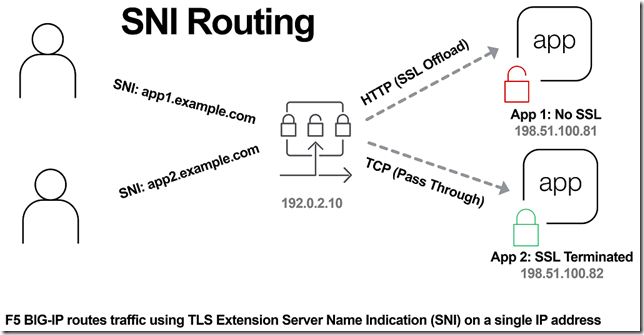
In the previous article, The Three HTTP Routing Patterns, Lori MacVittie covers 3 methods of routing. Today we will look at Server Name Indication (SNI) routing as an additional method of routing HTTPS or any protocol that uses TLS and SNI. Using SNI we can route traffic to a destination without having to terminate the SSL connection. This enables several benefits including: Reduced number of Public IPs Simplified configuration More intelligent routing of TLS traffic Terminating SSL Connections When you havea SSL certificate and key you can perform the cryptographic actions required to encrypt traffic using TLS. This is what I refer to as “terminating the SSL connection” throughout this article. When you want to route traffic this is a chickenand an egg problem, becausefor TLS traffic you want to be able to route the traffic by being able to inspect the contents, but this normally requires being able to “terminate the SSL connection”. The goal of this article is to layer in traffic routing for TLS traffic without having to require having/knowing the original SSL certificate and key. Server Name Indication (SNI) SNI is a TLS extension that makes it possible to "share" certificates on a single IP address. This is possible due to a client using a TLS extension that requests a specific name before the server responds with a SSL certificate. Prior to SNI, the other options would be a wildcard certificate or Subject Alternative Name (SAN) that allows you to specify multiple names with a single certificate. SNI with Virtual Servers It has been possible to use SNI on F5 BIG-IP since TMOS 11.3.0. The following KB13452 outlines how it can be configured. In this scenario (from the KB article) the BIG-IP is terminating the SSL connection. Not all clients support SNI and you will always need to specify a “fallback” profile that will be used if a SNI name is not used or matched. The next example will look at how to use SNI without terminating the SSL connection. SNI Routing Occasionally you may have the need to have a hybrid configuration of terminating SSL connections on the BIG-IP and sending connections without terminating SSL. One method is to create two separate virtual servers, one for SSL connections that the BIG-IP will handle (using clientssl profile) and one that it will not handle SSL (just TCP). This works OK for a small number of backends, but does not scale well if you have many backends (run out of Public IP addresses). Using SNI Routing we can handle everything on a single virtual server / Public IP address. There are 3 methods for performing SNI Routing with BIG-IP iRule with binary scan a. Article by Colin Walker code attribute to Joel Moses b. Code Share by Stanislas Piron iRule with SSL::extensions Local Traffic Policy Option #1 is for folks that prefer complete control of the TLS protocol. It only requires the use of a TCP profile. Options #2 and #3 only require the use of a SSL persistence profile and TCP profile. SNI Routing with Local Traffic Policy We will skip option #1 and #2 in this article and look at using a Local Traffic Policy for SNI Routing. For a review of Local Traffic Policies check out the following DevCentral articles: LTM Policy Jan 2015 Simplifying Local Traffic Policies in BIG-IP 12.1 June 2016 In previous articles about Local Traffic Policiesthe focus was on routing HTTP traffic, but today we will use it to route SSL connections using SNI. In the following example, using a Local Traffic Policy named “sni_routing”, we are setting a condition on the SSL Extension “servername” and sending the traffic to a pool without terminating the SSL connection. The pool member could be another server or another BIG-IP device. The next example will forward the traffic to another virtual server that is configured with a clientssl profile. This uses VIP targeting to send traffic to another virtual server on the same device. In both examples it is important to note that the “condition”/“action” has been changed from occurring on “request” (that maps to a HTTP L7 request) to “ssl client hello”. By performing the action prior to any L7 functions occurring, we can forward the traffic without terminating the SSL connection. The previous example policy, “sni_routing”, can be attached to a Virtual Server that only has a TCP profile and SSL persistence profile. No HTTP or clientssl profile is required! This method can also be used to solve the issue of how to consolidate multiple SSL virtual servers behind a single virtual server that have different APM and/or ASM policies. This is similar to the architecture that is used by the Container Connector for Cloud Foundry; in creating a two-tier load balancing solution on a single device. Routed Correctly? TLS 1.3 has interesting proposals on how to obscure the servername (TLS in TLS?), but for now this is a useful and practical method of handling multiple SSL certs on a single IP. In the future this may still be possible as well with TLS 1.3. For example the use of a HTTP Fronting service could be a tier 1 virtual server (this is just my personal speculation, I have not tried, at the time of publishing this was still a draft proposal). In other news it has been demonstrated that a combination of using SNI and a different host header can be used for “domain fronting”. A method to enforce consistent policy (prevent domain fronting) would be to layer in additional conditions that match requested SNI servername (TLS extension) with requested HOST header (L7 HTTP header). This would help enforce that a tenant is using a certificate that is associated with their application and not “borrowing” the name and certificate that is being used by an adjacent service. We don’t think of a TLS extension as an attribute that can be used to route application traffic, but it is useful and possible on BIG-IP.21KViews0likes16Comments
Securing and Scaling Hybrid Application with F5 NGINX (Part 1)
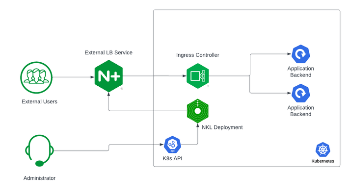
If you are using Kubernetes in production, then you are likely using an ingress controller. The ingress controller is the core engine managing traffic entering and exiting the Kubernetes cluster. Because the ingress controller is a deployment running inside the cluster, how do you route traffic to the ingress controller? How do you route external traffic to internal Kubernetes Services? Cloud providers offer a simple convenient way to expose Kubernetes Services using an external load balancer. Simply deploy a Managed Kubernetes Service (EKS, GKE, AKS) and create a Kubernetes Service of type LoadBalancer. The cloud providers will host and deploy a load balancer providing a public IP address. External users can connect to Kubernetes Services using this public entry point. However, this integration only applies to Managed Kubernetes Services hosted by cloud providers. If you are deploying Kubernetes in private cloud/on-prem environments, you will need to deploy your own load balancer and integrate it with the Kubernetes cluster. Furthermore, Kubernetes Load Balancing integrations in the cloud are limited to TCP Load Balancing and generally lack visibility into metrics, logs, and traces. We propose: A solution that applies regardless of the underlying infrastructure running your workloads Guidance around sizing to avoid bottlenecks from high traffic volumes Application delivery use cases that go beyond basic TCP/HTTP load balancing In the solution depicted below, I deploy NGINX Plus as the external LB service for Kubernetes and route traffic to the NGINX Ingress Controller. The NGINX Ingress Controller will then route the traffic to the application backends. The NLK (NGINX Load Balancer for Kubernetes) deployment is a new controller by NGINX that monitors specified Kubernetes Services and sends API calls to manage upstream endpoints of the NGINX External Load Balancer In this article, I will deploy the components both inside the Kubernetes cluster and NGINX Plus as the external load balancer. Note: I like to deploy both the NLK and Kubernetes cluster in the same subnet to avoid network issues. This is not a hard requirement. Prerequisites The blog assumes you have experience operating in Kubernetes environments. In addition, you have the following: Access to a Kubernetes environment; Bare Metal, Rancher Kubernetes Engine (RKE), VMWare Tanzu Kubernetes (VTK), Amazon Elastic Kubernetes (EKS), Google Kubernetes Engine (GKE), Microsoft Azure Kubernetes Service (AKS), and RedHat OpenShift NGINX Ingress Controller – Deploy NGINX Ingress Controller in the Kubernetes cluster. Installation instructions can be found in the documentation. NGINX Plus – Deploy NGINX Plus on VM or bare metal with SSH access. This will be the external LB service for the Kubernetes cluster. Installation instructions can be found in the documentation. You must have a valid license for NGINX Plus. You can get started today by requesting a 30-day free trial. Setting up the Kubernetes environment I start with deploying the back-end applications. You can deploy your own applications, or you can deploy our basic café application as an example. $ kubectl apply –f cafe.yaml Now I will configure routes and TLS settings for the ingress controller $ kubectl apply –f cafe-secret.yaml $ kubectl apply –f cafe-virtualserver.yaml To ensure the ingress rules are successfully applied, you can examine the output of kubectl get vs. The VirtualServer definition should be in the Valid state. NAMESPACE NAME STATE HOST IP PORTS default cafe-vs Valid cafe.example.com Setting up NGINX Plus as the external LB A fresh install of NGINX Plus will provide the default.conf file in the /etc/nginx/conf.d directory. We will add two additional files into this directory. Simply copy the bulleted files into your /etc/nginx/conf.d directory dashboard.conf; This will enable the real-time monitoring dashboard for NGINX Plus kube_lb.conf; The nginx configuration as the external load balancer for Kubernetes. You can change the configuration file to fit your requirements. In part 1 of this series, we enabled basic routing and TLS for one cluster. You will also need to generate TLS cert/keys and place them in the /etc/ssl/nginx folder of the NGINX Plus instance. For the sake of this example, we will generate a self-signed certificate with openssl. $ openssl req -x509 -nodes -days 365 -newkey rsa:2048 -keyout default.key -out default.crt -subj "/CN=NLK" Note: Using self-signed certificates is for testing purposes only. In a live production environment, we recommend using a secure vault that will hold your secrets and trusted CAs (Certificate Authorities). Now I can validate the configuration and reload nginx for the changes to take effect. $ nginx –t $ nginx –s reload I can now connect to the NGINX Plus dashboard by opening a browser and entering http://<external-ip-nginx>:9000/dashboard.html#upstreams The HTTP upstream table should be empty as we have not deployed the NLK Controller yet. We will do that in the next section. Installing the NLK Controller You can install the NLK Controller as a Kubernetes deployment that will configure upstream endpoints for the external load balancer using the NGINX Plus API. First, we will create the NLK namespace $ kubectl create ns nlk And apply the RBAC settings for the NKL deployment $ kubectl apply -f serviceaccount.yaml $ kubectl apply -f clusterrole.yaml $ kubectl apply -f clusterrolebinding.yaml $ kubectl apply -f secret.yaml The next step is to create a ConfigMap defining the API endpoint of the NGINX Plus external load balancer. The API endpoint is used by the NLK Controller to configure the NGINX Plus upstream endpoints. We simply modify the nginx-hosts field in the manifest from our GitHub repository to the IP address of the NGINX external load balancer. nginx-hosts: http://<nginx-plus-external-ip>:9000/api Apply the updated ConfigMap and deploy the NLK controller $ kubectl apply –f nkl-configmap.yaml $ kubectl apply –f nkl-deployment I can verify the NLK controller deployment is running and the ConfigMap data is applied. $ kubectl get pods –o wide –n nlk $ kubectl describe cm nginx-config –n nlk You should see the NLK deployment in status Running and the URL should be defined under nginx-hosts. The URL is the NGINX Plus API endpoint of the external load Balancer. Now that the NKL Controller is successfully deployed, the external load balancer is ready to route traffic to the cluster. The final step is deploying a Kubernetes Service type NodePort to expose the Kubernetes cluster to NGINX Plus. $ kubectl apply –f nodeport.yaml There are a couple things to note about the NodePort Service manifest. Fields on line 7 and 14 are required for the NLK deployment to configure the external load balancer appropriately: The nginxinc.io/nkl-cluster annotation The port name matching the upstream block definition in the NGINX Plus configuration (See line 42 in kube_lb.conf) and preceding nkl- apiVersion: v1 kind: Service metadata: name: nginx-ingress namespace: nginx-ingress annotations: nginxinc.io/nlk-cluster1-https: "http" # Must be added spec: type: NodePort ports: - port: 443 targetPort: 443 protocol: TCP name: nlk-cluster1-https selector: app: nginx-ingress Once the service is applied, you can note down the assigned nodeport selecting the NGINX Ingress Controller deployment. In this example, that node port is 32222. $ kubectl get svc –o wide –n nginx-ingress NAME TYPE CLUSTER-IP PORT(S) SELECTOR nginx-ingress NodePort x.x.x.x 443:32222/TCP app=nginx-ingress If I reconnect to my NGINX Pus dashboard, the upstream tab should be populated with the worker node IPs of the Kubernetes cluster and matching the node port of the nginx-ingress Service (32222). You can list the node IPs of your cluster to make sure they match the IPs in the dashboard upstream tab. $ kubectl get nodes -o wide | awk '{print $6}' INTERNAL-IP 10.224.0.6 10.224.0.5 10.224.0.4 Now I can connect to the Kubernetes application from our local machine. The hostname we used in our example (cafe.example.com) should resolve to the IP address of the NGINX Plus load balancer. Wrapping it up Most enterprises deploying Kubernetes in production will install an ingress controller. It is the DeFacto standard for application delivery in container orchestrators like Kubernetes. DevOps/NetOps engineers are now looking for guidance on how to scale out their Kubernetes footprint in the most efficient way possible. Because enterprises are embracing the hybrid approach, they will need to implement their own integrations outside of cloud providers. The solution we propose: is applicable to hybrid environments (particularly on-prem) Sizing information to avoid bottlenecks from large traffic volumes Enterprise Load Balancing capabilities that stretch beyond a TCP LoadBalancing Service In the next part of our series, I will dive into the third bullet point into much more detail and cover Zero Trust use cases with NGINX Plus, providing extra later of security in your hybrid model.169Views0likes0Comments