Distributed Cloud Support for NAS Migrations from On-Premises Approaches to Azure NetApp Files
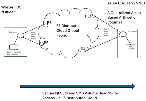
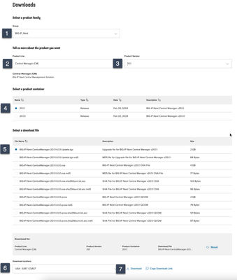
F5 Distributed Cloud (XC) Secure Multicloud Networking (MCN) connects and secures distributed applications across offices, data centers, and various cloud platforms. Frequently the technology is web-based, meaning traffic is often carried on ports like TCP port 443, however other traffic types are also prevalent in an enterprise’s traffic mix. Examples include SSH or relational database protocols. One major component of networked traffic is Network-Attached Storage (NAS), a protocol in the past frequently carried over LANs between employees in offices and co-located NAS appliances, perhaps in wiring closets or server rooms. An example of such an appliance would be the ONTAP family from NetApp which can take on physical or virtual form factors. NAS protocols are particularly useful as they integrate file stores into operating systems such as Microsoft Windows or Linux distributions as directories, mounted for easy access to files at any time, often permanently. This contrasts with SSH file transfers, which are often ephemeral actions and not so tightly integral to host operating system health. With the rise of remote work, often the NAS appliances see increasing file reads-and-writes to these directories, traversing wide-area links. In fact, one study analyzing fundamental traffic changes due to the Covid-19 pandemic saw a 22 percent increase in file transfer protocol (FTP) in a single year, suggesting access to files has undergone significant foundational changes in recent years. Distributed Cloud and the Movement towards Centralized Enterprise Storage A traditional concern about serving NAS files to offices from a centralized point, such as a cloud-instantiated file repository, is latency and reliability. With F5’s Distributed Cloud offering a 12 Tbps aggregate backbone and dedicated RE-to-RE links, the behavior of the network component is both highly durable and performant. The efficiencies of a centralized corporate file distribution point, with the required 9’s of guaranteed uptime of modern cloud services, and the logic of moving towards cloud-served NAS solutions makes a lot of sense. With on-premises storage appliances replaced by a secure, networked service eliminates the need to maintain costly spares, which are effectively a shadow NAS appliance infrastructure and onerous RMA procedures. All of this enables accomplishing the goal of shrinking/greening office wiring closets. To demonstrate this centralized model for a NAS architecture, a configuration was created whereby a west coast simulated office was connected by F5 Distributed Cloud to Azure NetApp Files (ANF) instantiated in Azure East-2 region. ANF is Microsoft Azure’s newest native file serving solution, managed by NetApp, with data throughputs that increase in lock step with the amount of reserved storage pool capacity. Different quality of service (QoS) levels are selectable by the consumer. In the streamlined ANF configuration workflow, where various transaction latency thresholds may be requested, even the most demanding relational database operations are typically accommodated. Microsoft offers additional details on ANF here, however, this article should serve to sufficiently demonstrate the ANF and F5 Distributed Cloud Secure MCN solutions for most readers. Distributed Cloud and Azure NetApp Files Deployment Example NAS in the enterprise today largely involves use of either NFS or SMB protocols, both of which can be used within Windows and Linux environments and make remote directories appear and perform as if local to users. In our example, a western US point of presence was leveraged to serve as the simulated remote office and standard Linux hosts to serve as the consumers of NetApp volumes. In the east, a corporate VNET was deployed in an Azure resource group (RG) in US-East-2, with one subnet delegated to provide Azure NetApp Files (ANF). To securely connect the west coast office to the eastern Azure ANF service, F5 Distributed Cloud Secure MCN was utilized to create a Layer 3 multi-cloud network offering. This is achieved by easily dropping an F5 customer edge (CE) virtual appliance into both the office and the Azure VNET in the east. The CE is a 2-port security appliance. The inside interfaces on both CEs were attached to a global virtual network, and exclusive layer-3 associations to allow simple connectivity and fully preserve privacy. In keeping with the promise of SaaS, Distributed Cloud users require no routing protocol setup. The solution takes care of the control plane, including routing and encryption. This concept could be scaled to hundreds of offices, if equipped with CEs, and easily attached to the same global virtual network. CEs, at boot-up, automatically attach via IP Sec (or SSL) tunnels to geographically close F5 backbone nodes, called regional edge (RE) sites. Like tunnel establishment, routing tables are updated under-the-hood to allow for a turn-key security relationship between Azure NetApp File volumes and consuming offices. The setup is depicted as follows: Setup Azure NetApp Files (ANF) Volumes in Minutes To put the centralized approach to offering NAS volumes for remote offices or locations into practice, a series of quick steps are undertaken, which can all be done through the standard Microsoft Azure portal. The four steps are listed below, with screenshots provided for key points in the brief process: If not starting from an existing Resource Group (RG), create a new RG and add an Azure VNET to it. Delegate one subnet in your VNET to support ANF. Under “Delegate Subnet to a Service” select from the pull-down-list the entry “Microsoft.NetApp/volumes”. Within the Resource Group, choose “Create” and make a NetApp account. This will appear in the Azure Marketplace listings as “Azure NetApp Files”. In your NetApp account, under “Storage service” create a capacity pool. The pool should be sized appropriately, larger is typically better, since numerous volumes, supporting your choice of NFS3/4 and SMB protocols, will be created from this single, large disk pool. Create your first volume, select size, NAS protocols to support, and QoS parameters that meet your business requirements. As seen below, when adding a capacity pool simply follow the numerical sequence to add your pool, with a newly created sample 2 TiB pool highlighted; 1,024 TiB (1 PiB) are possible (click image to enlarge). Interestingly, the capacity pool shown is the “Standard” service level, as opposed to “Premium” and “Ultra”. With QoS type of Auto selected, Azure NetApp Files provides increasing throughput in terms of megabytes per second as the number of TiB in the pool increases. The throughput also increases with service levels; for standard, as shown, 8 megabytes per second per TiB will be allocated. Beyond throughput, ANF also provides the lowest latency averages for reads and writes in the Azure portfolio of storage offerings. As such, ANF is a very good fit for database deployments that must see constrained, average latency for mission-critical transactions. Deeper discussion around ANF service levels may be explored through the Microsoft document here. The next screenshot shows the simple click-through sequence for adding a volume to the capacity pool, simply click on volumes and the “+Add volume” button. A resulting sample volume is displayed in the figure with key parameters highlighted. In the above volume (“f5-distributed-cloud-vol-001”) the NAS protocol selected was NFSv3 and the size of the volume (“Quota”) was set to 100GiB. Setup F5 Distributed Cloud Office-to-Azure Connectivity To access the volume in a secured and highly responsive manner, from corporate headquarters, remote offices or existing data centers, three items from F5 Distributed Cloud are required: A customer edge (CE) node, normally with 2-ports, must be deployed in the Azure RG VNET. This establishes the Azure instance as a “site” within the Distributed Cloud dashboard. Hub and spoke architectures may also be used if required, where VNET peering can also allow the secure multi-cloud network (MCN) solution to operate seamlessly. A CE is deployed at a remote office or datacenter, where file storage services are required by various lines of business. The CE is frequently deployed as a virtual appliance or installed on a bare metal server and typically has 2-ports. To instantiate a layer-3 MCN service, the inside ports of the two CEs are “joined” to a virtual global network created by the enterprise in the Distributed Cloud console, although REST API and Terraform are also deployment options. By having each inside port of the Azure and office CE’s joined to the same virtual network, the “inside” subnets can now communicate with each other, securely, with traffic normally exchanged over encrypted high-speed IPSec tunnels into the F5 XC global fabric. The following screenshot demonstrates adding the Azure CE inside interface to a global virtual network, allowing MCN connectivity to remote office clients requiring access to volumes. Further restrictions, to prevent unauthorized clients, are found within NAS protocols themselves, such as simple Export policies in NFS and ACL rules in SMB/CIFS, which can be configured quickly within ANF. Remote Office Access – Establish Read/Write File Access to Azure ANF over F5 Distributed Cloud With both ANF configured and F5 Distributed Cloud now providing a layer-3 muticloud network (MCN) solution, to patch enterprise offices to the centralized storage, some confirmation of the solution working as expected was desired. First off, a choice in protocols was made. When configuring ANF, the normal choices for access are NFSv3/v4 or SMB/CIFS or both protocols concurrently. Historically, Microsoft hosts made use of SMB/CIFS and Linux/Unix hosts preferred NFS, however today both protocols are used throughout enterprises. One example being long-time SAMBA server (SMB/CIFS) support in the world of Linux. Azure NetApp Files will provide all the necessary command samples to get hosts connected without difficulty. For instance, to mount the volume to a folder off the Linux user home directory, such as the sample folder “f5-distributed-cloud-vol-001”, per the ANF suggestion the following one command will connect the office Linux host to the central storage in Azure-East-2: sudo mount -t nfs -o rw,hard,rsize=262144,wsize=262144,vers=3,tcp 10.0.9.4:/f5-distributed-cloud-vol-001 f5-distributed-cloud-vol-001 At this point the volume is available for day-to-day tasks, including read and write operations, as if the NAS solution were local to the office, often literally down the hallway. Remote Office Access - Demonstration of Azure ANF over F5 Distributed Cloud in Action To repeatedly exercise file writes from a west coast US office to an east coast ANF deployment in Azure-East-2 (Richmond, Virgina) a simple shell script was used to perpetually write a file to a volume, delete it, and repeat over time. The following sample wrote a file of 20,000 bytes to the ANF service, waited a few seconds, and then removed the file before beginning another cycle. At the lowest common denominator, packet analysis for the ensuing traffic from the western US office will indicate both network and application latency sample values. As depicted in the following Wireshark trace, the TCP response to a transmitted segment carrying an NFS command, was observed to be just 74.5 milliseconds. This prompt round-trip latency for a cross-continent data plane suggests a performant Distributed Cloud MCN service level. This is easily seen as the offset from the reference timestamp (time equal to zero) of the NFS v3 Create Call. Click on image to expand. Analyzing the NAS response from ANF (packet 185) arrives less than 1 millisecond later, suggesting a very responsive, well-tuned NFS control plane offered by ANF. To measure the actual, write-time of a file from west coast to east coast, the following trace demonstrates the 20,000 byte file write exercise from the shell script. In this case, the TCP segments making up the file, specifically the large packet body lengths called out in the screenshot, are delivered efficiently without TCP retransmissions, TCP zero window events, nor having any indicators of layer 3 and 4 health concerns. The entirety of the write is measured at the packet layer to take only 150.8 milliseconds. Since packet-level analysis is not the most turnkey, easy method to monitor file read and write performance, a set of Linux and Windows utilities can also be leveraged. The Linux utility nfsiostat was concurrently used with the test file writes and produced similar, good latency measurements. Nfsiostat monitoring of the file write testing, from west coast to east coast, for the 20,000-byte file, has indicated an average write time to ANF of 151 milliseconds. The measurements presented here are simply observational, to present rapid, digestible techniques for readers interested in service assurance for running ANF over an XC L3 MCN offering. For more rigorous monitoring treatments, Microsoft provides guidance on performing one’s own measurements of Azure NetApp Files here. Summary As enterprise-class customers continue to rapidly look towards cloud for compute performance, GPU access, and economies-of-scale savings for key workloads, the benefits of a centralized, scalable storage counterpart to this story exists. F5 Distributed Cloud offers the reach and performance levels to securely tie existing offices and data centers to cloud-native storage solutions. One example of this approach to modernize storage was covered in this article, the turn-key ability to begin transitioning from traditionally on-premises NAS appliances to cloud-native scalable volumes. The Azure NetApp Files approach to serving read/write volumes allows modern hosts, including Windows and Linux distributions, to utilize virtually unlimited folder sizes with service levels adjustable to business needs.96Views0likes1CommentGetting Started with BIG-IP Next: Upgrading Central Manager
Upgrades are one of the major improvements in moving from BIG-IP classic to Next. Whereas there is no direct analog for Central Manager in BIG-IP classic, the improvements from the BIG-IP/BIG-IQ upgrade experience will be noticeable. Simplification is the goal, and in my first Central Manager upgrade experience, I'd say that bar has been reached. In this article, I'll walk you through performing an upgrade to a standalone Central Manager. When HA for Central Manager is released, I'll update this article with those details. The installation steps on Clouddocs (links in the resources at the end of this article) make note that you should upgrade your instances before Central Manager, so keep that in mind as you build out your procedure sets for BIG-IP Next operations. For production I'd also recommend taking a backup of Central Manager as well (I'll do a walkthrough of that process in the coming weeks) but for discovery on my BIG-IP Next journey, I'll skip that step and nuke/pave if I have an issue. The first step in the upgrade process is to download the BIG-IP Next Central Manager upgrade package. After you have the upgraded package, login to your Central Manager. Click in the upper left on the tic-tac-toe board. Then in the dropdown menu that appears, select the System option. There's only one option here currently, and that's the upgrade button. Go ahead and click it. There will be a couple notes on the new window about resources and information on the unavailability to perform tasks during the upgrade. Go ahead and click next. If you didn't grab the package yet, the link to do so is included on this menu page. I selected the upload file option, selected the package from my downloads, and uploaded the file. You'll get the "green means go" checkbox when it's ready, at which point you can click the upgrade button. On the "Are you sure?" alert dialog, go ahead and click yes, upgrade. At this point, the upgrade will begin. On my upgrade, session was grayed out and I could not interact with the Central Manager interface, so my session timed out. I had trouble getting back in for several minutes, but when I got back in, I was presented with this alert dialog. You can click close here. And with that, you can see the new version of code. Congratulations on your first upgrade of Central Manager. Resources Upgrade BIG-IP Next Central Manager257Views2likes3Comments
Securing and Scaling Hybrid apps with F5 NGINX (Part 2)
If you attended a cybersecurity trade-show lately, you may have noticed the term “Zero Trust (ZT)” advertised on almost every booth. It may seem like most security companies are offering the same value proposition: ‘Securing apps with ZT’. Its commonality stems from the fact that ZT is a broad term that can span endless use cases. ZT is not a feature or capability, rather a philosophy embraced by IT security leaders based on the idea that all traffic entering and exiting a system is not trusted and must be scrutinized before passing through. Organizations are shifting to a zero-trust mindset due to the increased complexity of cyber-attacks. Perimeter based firewalls are no longer sufficient in securing digital resources. In Part 1 of our series, we configured NGINX Plus as an external load balancer to route and terminate TLS traffic to cluster nodes. In this part of the series, we leverage the same NGINX Plus deployment to enable ZT use cases that will improve the security posture of your hybrid applications. NOTE: Part 1 of the series is a prerequisite for enabling the ZT use cases in our examples. Please ensure that part 1 is completed before starting with part 2 Part 1 of the series ZT Use case #1: OIDC Authentication OIDC (OpenID Connect) is an authentication layer on top of the OAuth 2.0 framework. Many organizations will choose OIDC to authenticate digital identities and enable SSO (Single-Sign-On) for consumer applications. With Single-Sign-on technologies, users gain access to multiple applications with one set of user credentials by authenticating their identities through an IdP (Identity Provider). I can configure NGINX Plus to operate as an OIDC relaying party to exchange and validate ID tokens with the IdP (Identity Provider), in addition to basic reverse-proxy load balancing configured in part 1. I will extend the architecture in part 1 with an IdP and configure NGINX Plus as the identity aware proxy. Prerequisites for NGINX Plus Before configuring NGINX Plus as the OIDC identity aware proxy: 1. Installation of NJS is required. $ sudo apt-get install nginx-plus-module-njs 2. Load the NJS module into the NGINX configuration by adding the following line at the top of yournginx.conf file. load_module modules/ngx_http_js_module.so; 3. Clone the OIDC GitHub repository in your directory of choice cd /home/ubuntu && git clone --branch R28 https://github.com/nginxinc/nginx-openid-connect.git Setting up the IdP The IdP will manage and store digital identities to mitigate attackers from impersonating users to steal sensitive information. There are many IdP vendors to choose from; Okta, Ping Identity, Azure AD. We chose Okta as the IdP in our example moving forward. If you do not have access to an IdP, you can quickly get started with the Okta Command Line Interface (CLI) and run the okta register command to sign up for a new account. Once account creation is successful, we will use the Okta CLI to preconfigure Okta as the IdP, creating what Okta calls an app integration. Other IdPs will have different nomenclatures defining an application integration. For example, Azure AD will call them App registrations. If you are not using Okta, you can follow the documentation of the IdP you are using and skip to the next section (Configuring NGINX as the OpenID Connect relying party). 1. Run the okta login command to authenticate the Okta Cli with your Okta developer account. Enter your Okta domain and API token at the prompts $ okta login Okta Org URL: https://your-okta-domain Okta API token: your-api-token 2. Create the app integration $ okta apps create --app-name=mywebapp --redirect-uri=https://<nginx-plus-hostname>:443/_codexch where --app-name defines the application name (here, mywebapp) --redirect-uri defines the URI to which sign-ins are redirected to the NGINX Plus. <nginx-plus-hostname> should resolve to the NGINX Plus external IP configured in part 1. We use port 443 since TLS termination is configured on NGINX Plus from part 1. Recall we used self-signed certificates and keys to configure TLS on NGINX Plus. In a production environment, we recommend using certs/keys issued by a trusted certificate authority such as Let’s Encrypt. Once the command from step #2 is completed, the client ID and Secret generated from the app integration can be found in ${HOME}/.okta.env Configuring NGINX as the OpenID Connect relying party Now that we have finished setting up our IdP, we can now start configuring NGINX Plus as the OpenID Connect relying party. Once logged into the NGINX Plus instance, simply run the configuration script from your home directory. $ ./nginx-openid-connect/configure.sh -h <nginx-plus-hostname> -k request -i <YOURCLIENTID> -s <YOURCLIENTSECRET> –xhttps://dev-xxxxxxx.okta.com/.well-known/openid-configuration where -h defines the hostname of NGINX Plus -k defines how NGINX will retrieve JWK files to validate JWT signatures. The JWK file is retrieved from a subrequest to the IdP -i defines the Client ID generated from the IdP -s defines the Client Secret generated from the IdP -x defines the URL of the OpenID configuration endpoint. Using Okta as the example, the URL starts with your Okta organization domain, followed by the path URI /.well-known/openid-configuration The configure script will generate OIDC config files for NGINX Plus. We will copy the generated config files into the /etc/nginx/conf.d directory from part 1. $ sudo cp frontend.conf openid_connect.js openid_connect.server_conf openid_connect_configuration.conf /etc/nginx/conf.d/ You will notice by default that frontend.conf listens on port 8010 with clear text http. We need to merge kube_lb.conf into frontend.conf to enable both use cases from part 1 and 2. The resulting frontend.conf should look something like this: https://gist.github.com/nginx-gists/af067326734063da6a4ff42146873262 Finally, I will need to edit the openid_connect_configuration.conf file and modify my client secret to the one generated by my Okta IdP. Reload NGINX Plus for the new config to take effect. $ nginx -s reload Testing the Environment Now we are ready to test our environment in action. To summarize, we set up an IdP and configured NGINX Plus as the identity aware proxy to validate user ID tokens before the entering the Kubernetes cluster. To test the environment, we will open a browser and enter the hostname of NGINX Plus into the address field. You should be redirected to your IdP login page. Note: The host name should resolve to the Public IP of the NGINX Plus machine. Once you are prompted with the IdP login page from your browser, you can access the Kubernetes pods once the user credentials are validated. User credentials should be defined from the IdP. Once you are logged into your application, the ID token of the authenticated is stored in the NGINX Plus Key-Value Store. Enabling PKCE with OIDC In the previous section, we learned how to configure NGINX Plus as the OIDC relying party to authenticate user identities attempting connections to protected Kubernetes applications. However, there are few cases where attackers can intercept code exchange requests issued from the IdP and hijack your ID tokens and gain access to your sensitive applications. PKCE is an extension of the OIDC Authorization code flow designed to protect against authorization code interception and theft. PKCE provides an extra layer of security where the attacker will need to provide a code verifier in addition to the authorization code in exchange for the ID token from the IdP. In our current setup, NGINX Plus will send a random generated PKCE code verifier as a query parameter when redirecting users to the IdP login page. The IdP will use this PKCE code verifier as extra validation when the authorization code is exchanged for the ID token. PKCE needs to be enabled from both NGINX Plus and the IdP. To enable PKCE verification on NGINX Plus, edit the openid_connect_configuration.conf file and modify $oidc_pkce_enable to 1 and reload NGINX Plus. Depending on the IdP you are using, a checkbox should be available to enable PKCE. Testing the Environment To test that PKCE is working, we will open a browser and enter the NGINX Plus host name once again. You should be redirected to the login page, only this time you will notice the URL had slightly changed with additional query parameters: code_challenge_method – Method used to hash the plain code verifier (most likely SHA256) code_challenge – The hashed value of the plain code verifier NGINX Plus will provide this plain code verifier along with the authorization code in exchange for the ID token. NGINX Plus will then validate the ID token and store it in cache. Extending OIDC with 3rd party Systems Customers may need to integrate their OIDC workflow with proprietary Auth/Auth systems already in production. For example, additional metadata pertaining to a user may need to be collected from an external Redis Cache or JFrog Artifactory. We can fill this gap by extending our diagram from the previous section. In addition to token validation with NGINX Plus, I pull response data from JFrog Artifactory and pass it to the backend applications once users are authenticated. Note: I am using JFrog Artifactory as an example 3rd party endpoint here. I can technically use any endpoint I want. Testing the Environment To test our environment in action, I will make a few updates to my NGINX OIDC configuration. You can pull our updated GitHub repository and use it as reference for updating your NGINX configuration. Update #1: Adding the njs source code The first update is extending NGINX Plus with njs and retrieving response data from our 3rd party system. Add the KvOperations.js source file in your /etc/nginx/njs directory. Update #2: frontend.conf I am adding lines 37-39 to frontend.conf so that NGINX Plus will initiate the sub-request to our 3rd party system after users are authenticated with OIDC. We are setting the URI of this sub-request to /kvtest. More on this on the next update. Update #3: openid_connect.server_conf We are adding lines 35-48 to openid_connect.server_conf consisting of two internal redirects in NGINX: /kvtest; Internal redirect from sub-requests with URI /kvtest will functions in KvOperations.js /auth; Internal redirect for sub-requests with URI /authwill be proxied to the 3rd party endpoint. You can replace the <artifactory-url> in line 47 with your own endpoints Update #4: openid_connect_configuration.conf This update is optional and applies when passing dynamic variables to your 3rd party endpoints. You can dynamically update variables on the fly by sending POST requests to the NGINX Plus Key-Value store. $ curl -iX POST -d '{"admin", "<input-value>"}' http://localhost:9000/api/7/http/<keyval-zone-name> We are defining/instantiating the new Key-Value store in lines 102-104.Once the updates are complete, I can test the optimized OIDC environment by troubleshooting/verifying the application is on the receiving end of my dynamic input values. Wrapping it up I covered a subset of ZT use cases with NGINX in hybrid architectures. The use cases presented in this article center around authentication. In the next part of our series, I will cover more ZT use case that include: Alternative authentication methods (SAML) Encryption Authorization and Access Control Monitoring/Auditing173Views0likes0CommentsMitigating Application Threats with BIG-IP Next WAF
Overview of BIG-IP Next In today's modern world where the digital landscape is continuously evolving and security threats are becoming more sophisticated, the need for a robust and adaptive security solution is essential. BIG-IP Next is a next-generation solution which is setting a new standard for safeguarding your digital assets, protecting your applications, and empowering enterprises with the highest security efficacy.BIG-IP Next is the modernized solution optimized to simplify operations, enhance performance, and strengthen security. As per the official website, BIG-IP Next simplifies day-to-day ADC operations and accelerates application time-to-market through automation so that you can focus more on getting your apps online. BIG-IP Next’s modern, highly scalable software architecture is designed for maximum resiliency to support vast, dynamic application portfolios and their most complex traffic management and security policies, ensuring that applications are always available to end users. BIG-IP Next also provides deep insights into your application health, network performance, traffic patterns, and security threats to improve business decision-making. For a quick overview of BIG-IP Next and how the next-generation attributes can help you with your existing or new deployments, check out the video below. Here are some of the key capabilities that you can checkout and learn how you can mitigate app threats and security complexity with BIG-IP Next WAF: 1. Deploy HTTPS application with WAF Protection The first step in protecting your applications starts with onboarding your application in BIG-IP Next instance and creating a WAF security policy as per application requirements. Finally creating load balancers and applying the above-created WAF policies. Next, users can monitor the application traffic by navigating to their respective security dashboards and take necessary steps as per security insights. For more details, see this video. 2. Create and Manage Security Policies Sometimes creating security policies can be a time-consuming job, and BIG-IP Next has made this user-friendly for creating and managing security policies from a centralized UI. Users can create, delete or update their existing policies in fewer steps and can apply them directly to the applications, thereby decreasing the application delivery time to market. You can check out the video below for more details. 3. Create Security Policies using Templates One more advantage of BIG-IP Next is the support for creating security policies using templates and it’s just a one-click action using 'F5 BIG-IP Next’. Users can make use of default templates and protect their applications with zero effort, for ex. Using the Violation Rating Template. For more information, check below video. 4. Security Policy Migration Going through existing BIG-IP security policies and then creating the same ones in BIG-IP Next solution can be time-consuming. This is made easy so that users can migrate their security policy from 'F5 Advanced WAF' to 'F5 BIG-IP Next WAF' in a simple manner. With fewer steps, you can have your entire WAF security posture up without going through the rough step of creating them from scratch. Please refer to the video below for more insights. 5. Signatures and Threat Campaigns Update Regular update of attack signatures and threat campaigns is a vital step in safeguarding your applications against the latest attacks. This process is super easy using ‘F5 BIG-IP Next’ so that applications can mitigate them without the need for downtime. For step-by-step procedure to update signatures and threat campaigns, please check the video below. You can also check out the demo link below for detailed insights of how BIG-IP Next WAF enables the migration of apps and policies between BIG-IP TMOS and BIG-IP Next. The demo also shows how to deploy new web applications with WAF security policies included within BIG-IP Next Central Manager and finally how to analyze and respond to security incidents within the Next WAF dashboard. Reference links What is BIG-IP Next? | DevCentral Getting Started with BIG-IP Next: Fundamentals | DevCentral https://www.f5.com/products/big-ip-services/big-ip-next 124Views0likes0Comments
What is BIG-IP Next?
BIG-IP Next LTM and BIG-IP Next WAF hit general availability back in October, and we hit the road for a tour around North America for its arrival party! Those who attended one of our F5 Academy sessions got a deep-dive presentation into BIG-IP Next conceptually, and then a lab session to work through migrating workloads and deploying them. I got to attend four of the events and discuss with so many fantastic community members what's old, what's new, what's borrowed, what's blue...no wait--this is no wedding! But for those of us who've been around the block with BIG-IP for a while, if not married to the tech, we definitely have a relationship with it, for better and worse, right? And that's earned. So any time something new, or in our case "Next" comes around, there's risk and fear involved personally. But don't fret. Seriously. It's going to be different in a lot of ways, but it's going to be great. And there are a crap-ton (thank you Mark Rober!) of improvements that once we all make it through the early stages, we'll embrace and wonder why we were even scared in the first place. So with all that said, will you come on the journey with me? In this first of many articles to come from me this year, I'll cover the high-level basics of what is so next about BIG-IP Next, and in future entries we'll be digging into the tech and learning together. BIG-IP and BIG-IP Next Conceptually - A Comparison BIG-IP has been around since before the turn of the century (which is almost old enough to rent a car here in the United States) and this year marks the 20 year anniversary of TMOS. That the traffic management microkernel (TMM) is still grokking like a boss all these years later is a testament to that early innovation! So whereas TMOS as a system is winding down, it's heart, TMM, will go on (cue sappy Celine Dion ditty in 3, 2, 1...) Let's take a look at what was and what is. With TMOS, the data plane and control plane compete for resources as it's one big system. With BIG-IP, the separation of duties is more explicit and intentionally designed to scale on the control plane. Also, the product modules are no longer either completely integrated in TMM or plugins to TMM, but rather, isolated to their own container structures. The image above might convey the idea that LTM or WAF or any of the other modules are single containers, but that's just shown that way for brevity. Each module is an array of containers. But don't let that scare you. The underlying kubernetes architecture is an abstraction that you may--but certainly are not required to--care about. TMM continues to be its awesome TMM self. The significant change operationally is how you interact with BIG-IP. With TMOS, historically you engage directly with each device, even if you have some other tools like BIG-IQ or third-party administration/automation platforms. With BIG-IP Next, everything is centralized on Central Manager, and the BIG-IP Next instances, whether they are running on rSeries, VELOS, or Virtual Edition, are just destinations for your workloads. In fact, outside of sidecar proxies for troubleshooting, instance logins won't even be supported! Yes, this is a paradigm shift. With BIG-IP Next, you will no longer be configuration-object focused. You will be application-focused. You'll still have the nerd-knobs to tweak and turn, but they'll be done within the context of an application declaration. If you haven't started your automation journey yet, you might not be familiar with AS3. It's been out now for years and works with BIG-IP to deploy applications declaratively. Instead of following a long pre-flight checklist with 87 steps to go from nothing to a working application, you simply define the parameters of your application in a blob of JSON data and click the easy button. For BIG-IP Next, this is the way. Now, in the Central Manager GUI, you might interact with FAST templates that deliver a more traditional view into configuring applications, but the underlying configuration engine is all AS3. For more, I hosted aseries of streams in December to introduce AS3 Foundations, I highly recommend you take the time to digest the basics. Benefits I'm Excited About There are many and you can read about them on the product page on F5.com. But here's my short list: API-first. Period. BIG-IP had APIs with iControl from the era before APIs were even cool, but they were not first-class citizens. The resulting performance at scale requires effort to manage effectively. Not only performance, but feature parity among iControl REST, iControl SOAP, tmsh, and the GUI has been a challenge because of the way development occurred over time. Not so with BIG-IP Next. Everything is API-first, so all tooling is able to consume everything. This is huge! Migration assistance. Central Manager has the JOURNEYS tool on sterroids built-in to the experience. Upload your UCS, evaluate your applications to see what can be migrated without updates, and deploy! It really is that easy. Sure, there's work to be done for applications that aren't fully compatible yet, but it's a great start. You can do this piece (and I recommend that you do) before you even think about deploying a single instance just to learn what work you have ahead of you and what solutions you might need to adapt to be ready. Simplified patch/upgrade process. If you know, you know...patches are upgrades with BIG-IP, and not in place at that. This is drastically improved with BIG-IP Next! Because of the containerized nature of the system, individual containers can be targeted for patching, and depending on the container, may not even require a downtime consideration. Release cycle. A more frequent release cadence might terrify the customers among us that like to space out their upgrades to once every three years or so, but for the rest of us, feature delivery to the tune of weeks instead of twice per year is an exciting development (pun intended!) Features I'm Excited About Versioning for iRules and policies. For those of us who write/manage these things, this is huge! Typically I'd version by including it in the title, and I know some who set release tags in repos. With Central Manager, it's built-in and you can deploy iRules and polices by version and do diffs in place. I'm super excited about this! Did I mention the API? On the API front...it's one API, for all functionality. No digging and scraping through the GUI, tmsh, iControl REST, iControl SOAP, building out a node.js app to deploy a custom API endpoint with iControl LX, if even possible with some of the modules like APM or ASM. Nope, it's all there in one API. Glorious. Centralized dashboards. This one is for the Ops teams! Who among us has spent many a day building custom dashboards to consume stats from BIG-IPs across your org to have a single pane of glass to manage? I for one, and I'm thrilled to see system, application, and security data centralized for analysis and alerting. Log/metric streaming. And finally, logs and metrics! Telemetry Streaming from the F5 Automation Toolchain doesn't come forward in BIG-IP Next, but the ideas behind it do. If you need your data elsewhere from Central Manager, you can set up remote logging with OpenTelemetry (see the link in the resources listed below for a first published example of this.) There are some great features coming with DNS, Access, and all the other modules when they are released as well. I'll cover those when they hit general availability. Let's Go! In the coming weeks, I'll be releasing articles on installation and licensing walk-throughs for Central Manager and the instances, andcontent from our awesome group of authors is already starting to flow as well. Here are a few entries you can feast your eyes on, including an instance Proxmox installation: For the kubernetes crowd, BIG-IP Next CNF Solutions for RedHat Openshift Installing BIG-IP Next Instance on Proxmox Remote Logging with BIG-IP Next and OpenTelemetry Are you ready? Grab a trial licensefrom your MyF5 dashboard and get going! And make sure to join us in the BIG-IP Next Academy group here on DevCentral. The launch team is actively engaged there for next-related questions/issues, so that's the place to be in your early journey! Also...if you want the ultimate jump-start for all things BIG-IP Next, join usatAppWorld 2024 in SanJose next month!3.8KViews17likes5CommentsCreate F5 BIG-IP Next Instance on Proxmox Virtual Environment
If you are looking to deploy a F5 BIG-IP Next instance on Proxmox Virtual Environment (henceforth referred to as Proxmox for the sake of brevity), perhaps in your home lab, here's how: First, download the BIG-IP Next OVA File from MyF5 Downloads. Copy the OVA file to your Proxmox host. I am using SCP in the example below. local $ scp BIG-IP-Next-20.0.1-2.139.10+0.0.136.ovf root@proxmox:~/ On the Proxmox host, extract the contents in the OVA file: proxmox $ cd ~/ proxmox $ tar -xvf BIG-IP-Next-20.0.1-2.139.10+0.0.136.ova BIG-IP-Next-20.0.1-2.139.10+0.0.136.ovf BIG-IP-Next-20.0.1-2.139.10+0.0.136.mf BIG-IP-Next-20.0.1-2.139.10+0.0.136.cert BIG-IP-Next-20.0.1-2.139.10+0.0.136-disk1.vmdk Then, run the command below to create a virtual machine (VM) from the extracted OVF file. <vm_id> should be an unused ID on Proxmox. # qm importovf <vm_id> BIG-IP-Next-20.0.1-2.139.10+0.0.136.ovf local-lvm proxmox $ qm importovf 112 BIG-IP-Next-20.0.1-2.139.10+0.0.136.ovf local-lvm Logical volume "vm-112-disk-0" created. transferred 0.0 B of 80.0 GiB (0.00%) transferred 819.2 MiB of 80.0 GiB (1.00%) transferred 1.6 GiB of 80.0 GiB (2.00%) <output truncated> transferred 80.0 GiB of 80.0 GiB (100.00%) transferred 80.0 GiB of 80.0 GiB (100.00%) You should now see a new VM created on the Proxmox GUI. Before starting the VM, we need to attach a few hardware components to the VM: a Network Device for the management interface one or more additional Network Devices for the data plane interfaces (e.g. internal and external). Note that the data plane Network Devices must be of VirtIO model Optionally, you could also configure CLI access with the following instructions Finally, start the VM. This will take a few minutes. If CLI access is available, open up the console and run kubectl get pods until you can see all pods are ready. The BIG-IP Next VM is now ready to be onboarded per instructions found here.1.6KViews6likes2CommentsHow to get a F5 BIG-IP VE Developer Lab License
(applies to BIG-IP TMOS Edition) To assist DevOps teams improve their development for the BIG-IP platform, F5 offers a low cost developer lab license.This license can be purchased from your authorized F5 vendor. If you do not have an F5 vendor, you can purchase a lab license online: CDW BIG-IP Virtual Edition Lab License CDW Canada BIG-IP Virtual Edition Lab License Once completed, the order is sent to F5 for fulfillment and your license will be delivered shortly after via e-mail. F5 is investigating ways to improve this process. To download the BIG-IP Virtual Edition, please log into downloads.f5.com (separate login from DevCentral), and navigate to your appropriate virtual edition, example: For VMware Fusion or Workstation or ESX/i:BIGIP-16.1.2-0.0.18.ALL-vmware.ova For Microsoft HyperV:BIGIP-16.1.2-0.0.18.ALL.vhd.zip KVM RHEL/CentoOS: BIGIP-16.1.2-0.0.18.ALL.qcow2.zip Note: There are also 1 Slot versions of the above images where a 2nd boot partition is not needed for in-place upgrades. These images include_1SLOT- to the image name instead of ALL. The below guides will help get you started with F5 BIG-IP Virtual Edition to develop for VMWare Fusion, AWS, Azure, VMware, or Microsoft Hyper-V. These guides follow standard practices for installing in production environments and performance recommendations change based on lower use/non-critical needs fo Dev/Lab environments. Similar to driving a tank, use your best judgement. DeployingF5 BIG-IP Virtual Edition on VMware Fusion Deploying F5 BIG-IP in Microsoft Azure for Developers Deploying F5 BIG-IP in AWS for Developers Deploying F5 BIG-IP in Windows Server Hyper-V for Developers Deploying F5 BIG-IP in VMware vCloud Director and ESX for Developers Note: F5 Support maintains authoritativeAzure, AWS, Hyper-V, and ESX/vCloud installation documentation. VMware Fusion is not an official F5-supported hypervisor so DevCentral publishes the Fusion guide with the help of our Field Systems Engineering teams.74KViews13likes143CommentsGetting Started with BIG-IP Next: Configuring Instance High Availability
With BIG-IP classic, there are a lot of design choices to make and steps on both systems to arrive at an HA pair. With BIG-IP Next, this is simplified quite a bit. Once configured, the highly available pair is treated by Central Manager as a single entity. There might be alternative options in the future, but as of version 20.1, HA for instances is active/standby only. In this article, I'll walk you through the steps to configure HA for instances in the Central Manager GUI. Background and Prep Work I set up two HA systems in my preparation for this article. The first had dedicated interfaces for the management interface, the external and internal traffic interfaces, and the HA interface. So when configuring the virtual machine, I made sure each system had four NICs. For the second, I merged all the non-management interfaces on a single NIC and used vlan tagging, so those systems had two NICs. In my lab that looks like this: The IP addressing scheme in my lab is shown below. First the four NIC system: 4-NIC System next-4nic-a next-4nic-b floating mgmt 172.16.2.152/24 172.16.2.153/24 172.16.2.151/24 cntrlplane ha (vlan 245) 10.10.245.1/30 10.10.245.2/30 NA dataplane ha (int 1.3) 10.0.5.1/30 10.0.5.2/30 NA dataplane ext (int 1.1) 10.0.2.152/24 10.0.2.153/24 10.0.2.151/24 dataplane int (int 1.2) 10.0.3.152/24 10.0.3.153/24 10.0.3.151/24 And now the two NIC system: 2-NIC System next-2nic-a next-2nic-b floating mgmt 172.16.2.162/24 172.16.2.163/24 172.16.2.161/24 cntrlplane ha (vlan 245) 10.10.245.5/30 10.10.245.6/30 NA dataplane ha (vlan 50) 10.0.5.5/30 10.0.5.6/30 NA dataplane ext (vlan 30) 10.0.2.162/24 10.0.2.163/24 10.0.2.161/24 dataplane int (vlan 40) 10.0.3.162/24 10.0.2.163/24 10.0.3.161/24 Beyond the self IP addresses for your traffic interfaces, you'll need additional IP addresses for the floating address, the control-plane HA sub-interfaces (which are created for you), and teh data-plane HA interfaces. Before proceeding, make sure you have a plan for network segmentation and addressing similar to above, you've installed two like instances, and that one (and only one) of them is licensed. Configuration This walk through is for the 2-NIC system shown above, but the steps are mostly the same. First, login to Central Manager, and click on Manage Instances. Click on the standalone mode for the system you want to be active initially in your HA pair. For me, that's next-2nic-a. (You can also just click on the system name and then select HA in the menu, but this saves a click.) In the pop-up dialog, select Enable HA. Read the notes below to make sure your systems are ready to be paired. On this screen, a list of available standalone systems will populate. Click the down arrow and select your second system, next-2nic-b in my case. Then click Next. On this next prompt, you'll need to create two vlans, one for the control plane and one for the data plane. The control plane mechanics are taken care of for you and you don't need to plan connectivity other than to select an available vlan that won't conflict with anything else in your system. For the data plane, you need to have a dedicated vlan and/or interface set aside. Click Create VLAN for the control plane. Name and tag your vlan. In my case I used cp-ha as my vlan name and tag 245. Click Done. Now click Create VLAN for the data plane. Because I'm tagging all networks on the 2-NIC system, my own interface is 1.1. So I named my data plan vlan dp-ha, set the tag to 50, selected interface 1.1, and clicked Done. Now that both HA VLANs have been created, click Next. On this screen, you'll name your HA pair system. This will need to be unique from other HA pairs, so plan accordingly. I named mine next-ha-1, but that's generic and unlikely to be helpful in your environment. Then set your HA management IP, this is how Central Manager will connect to the HA pair. You can enable auto-failback if desired, but I left that unchecked. For the HA Nodes Addresses, I referenced my addressing table posted at the top of this article and filled those in as appropriate. When you get those filled out, click Next. Now you'll be presented with a list of your traffic VLANs. On my system I have v102-ext and v103-int for my external and internal networks. First, I clicked v102-ext. On this screen you'll need to add a couple rows so you can populate the active node IP, the standby node IP, and the floating IP. The order doesn't matter, but I ordered them as shown, and again referenced my addressing table. Once populated, click Save. That will return you to this screen, where you'll notice that v102-ext now has a green checkbox where the yellow warning was. Now click into your other traffic VLAN (v103-int in my case) if applicable to your environment or skip this next step. This is a repeat of the external traffic network for the internal traffic network. I referenced my address table one more time and filled the details out as appropriate, then clicked Save. Make sure that you have green checkboxes on the traffic VLANs, then click Next. Review the summary of the HA settings you've configured, and if everything looks right, click Deploy to HA. On the "are you sure?" dialog where you're prompted to confirm your deployment, click Yes, Deploy. You'll then see messaging at the top of the HA configuration page for the instance indicating that HA is being created. Also note that the Mode on this page during creation still indicates standalone. Once the deployment is complete, you'll see the mode has changed to HA and the details for your active and standby nodes are provided. Also present here is the Enable automatic failover option, which is enabled by default. This is for software upgrades. If left enabled, the standby unit will be upgraded first, a failover will be executed, and the the remaining system will be upgraded. If in your HA configuration you specified auto-failback, then after the second system is upgraded there will be another failover executed to complete the process. And finally, as seen in the list of instances, there are three now instead of four, with next-ha-1 taking the place of next-2nic-a and next-2nic-b from where we started. Huzzah! You now have a functioning BIG-IP Next HA pair. After we conclude the "Getting Started" series, we'll start to look at the benefits of automation around all the tasks we've covered so far, including HA. The click-ops capabilities are nice to have, but I think you'll find the ability to automate all this from a script or something like an Ansible playbook will really start to drive home the API-first aspects of Next.438Views1like1CommentGetting Started with BIG-IP Next: Licensing Instances in Central Manager
This article assumes that the license was not applied during the initial instance setup. Download the JSON Web Token from MyF5 I don't have a paid license, so I'm going to use my trial license available at MyF5. Your mileage may vary here. Go to my products & plans, trials, and then in the my trials listing (assuming you've requested/received one) click BIG-IP Next. Click downloads and licenses (note, however, the helpful list of resources down in guides and references). You can just copy your JSON web token, but I chose to download. Install the Token Login to Central Manager and click manage instances. Click on your new unlicensed instance. In the left-hand menu at the bottom, click License. Click activate license. We already downloaded our token, so after reviewing the information, click next. Note that I made sure that my Central Manager has access to the licensing server and the steps covered in this article assume the same. If you've managed classic BIG-IP licenses, copying and pasting dossiers to get licenses should be a well-understood process. On this screen, paste your token into the box, give it a name, and click activate. After a brief interrogation of the licensing server, you should now have a healthy, licensed, BIG-IP Next Instance! Resources How to: Manage BIG-IP Next instance licenses418Views0likes6Comments