Kubernetes architecture options with F5 Distributed Cloud Services
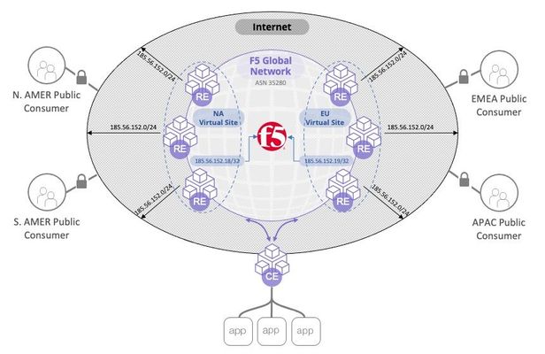
Summary F5 Distributed Cloud Services (F5 XC) can both integrate with your existing Kubernetes (K8s) clustersand/or host aK8s workload itself. Within these distinctions, we have multiple architecture options. This article explores four major architectures in ascending order of sophistication and advantages. Architecture #1: External Load Balancer (Secure K8s Gateway) Architecture #2: CE as a pod (K8s site) Architecture #3: Managed Namespace (vK8s) Architecture #4: Managed K8s (mK8s) Kubernetes Architecture Options As K8s continues to grow, options for how we run K8s and integrate with existing K8s platforms continue to grow. F5 XC can both integrate with your existing K8s clustersand/orrun a managed K8s platform itself.Multiple architectures exist within these offerings too, so I was thoroughly confused when I first heard about these possibilities. A colleague recently laid it out for me in a conversation: "Michael, listen up: XC can eitherintegrate with your K8s platform,run insideyour K8s platform, host virtual K8s(Namespace-aaS), or run a K8s platformin your environment." I replied, "That's great. Now I have a mental model for differentiating between architecture options." This article will overview these architectures and provide 101-level context: when, how, and why would you implement these options? Side note 1: F5 XC concepts and terms F5 XC is a global platform that can provide networking and app delivery services, as well as compute (K8s workloads). We call each of our global PoP's a Regional Edge (RE). RE's are highly meshed to form the backbone of the global platform. They connect your sites, they can expose your services to the Internet, and they can run workloads. This platform is extensible into your data center by running one or more XC Nodes in your network, also called a Customer Edge (CE). A CE is a compute node in your network that registers to our global control plane and is then managed by a customer as SaaS. The registration of one or more CE's creates a customer site in F5 XC. A CE can run on ahypervisor (VMWare/KVM/Etc), a Hyperscaler (AWS, Azure, GCP, etc), baremetal, or even as a k8s pod, and can be deployed in HA clusters. XC Mesh functionality provides connectivity between sites, security services, and observability. Optionally, in addition, XC App Stack functionality allows a large and arbitrary number of managed clusters to be logically grouped into a virtual site with a single K8s mgmt interface. So where Mesh services provide the networking, App Stack services provide the Kubernetes compute mgmt. Our first 2 architectures require Mesh services only, and our last two require App Stack. Side note 2: Service-to-service communication I'm often asked how to allow services between clusters to communicate with each other. This is possible and easy with XC. Each site can publish services to every other site, including K8s sites. This means that any K8s service can be reachable from other sites you choose. And this can be true in any of the architectures below, although more granular controls are possible with the more sophisticated architectures. I'll explore this common question more in a separate article. Architecture 1: External Load Balancer (Secure K8s Gateway) In a Secure Kubernetes Gatewayarchitecture, you have integration with your existing K8s platform, using the XC node as the external load balancer for your K8s cluster. In this scenario, you create a ServiceAccount and kubeconfig file to configure XC. The XC node then performs service discovery against your K8s API server. I've covered this process in a previous article, but the advantage is that you can integrate withexisting K8s platforms. This allows exposing both NodePort and ClusterIP services via the XC node. XC is not hosting any workloads in this architecture, but it is exposing your services to your local network, or remote sites, or the Internet. In the diagram above, I show a web application being accesssed from a remote site (and/or the Internet) where the origin pool is a NodePort service discovered in a K8s cluster. Architecture 2: Run a site within a K8s cluster (K8s site type) Creating a K8s site is easy - just deploy a single manifest found here. This file deploys multiple resources in your cluster, and together these resources work to provide the services of a CE, and create a customer site. I've heard this referred to as "running a CE inside of K8s" or "running your CE as a pod". However, when I say "CE node" I'm usually referring to a discreet compute node like a VM or piece of hardware; this architecture is actually a group of pods and related resources that run within K8s to create a XC customer site. With XC running inside your existing cluster, you can expose services within the cluster by DNS name because the site will resolve these from within the cluster. Your service can then be exposed anywhere by the F5 XC platform. This is similar to Architecture 1 above, but with this model, your site is simply a group of pods within K8s. An advantage here is the ability to expose services of other types (e.g. ClusterIP). A site deployed into a K8s cluster will only support Mesh functionality and does not support AppStack functionality (i.e., you cannot run a cluster within your cluster). In this architecture, XC acts as a K8s ingress controller with built-in application security. It also enables Mesh features, such as publishing of other sites' services on this site, and publishing of this site's discovered services on other sites. Architecture 3: vK8s (Namespace-as-a-Service) If the services you use includeAppStack capabilities, then architectures #3 and #4 are possible for you.In these scenarios, our XC nodeactually runs your K8son your workloads. We are no longer integrating XC with your existing K8s platform. XCisthe platform. A simple way to run K8s workloads is to use avirtual k8s (vK8s) architecture. This could be referred to as a "managed Namespace" because by creating a vK8s object in XC you get a single namespace in a virtual cluster. Your Namespace can be fully hosted (deployed to RE's) or run on your VM's (CE's), or both. Your kubeconfig file will allow access to your Namespace via the hosted API server. Via your regular kubectl CLI (or via the web console) you can create/delete/manage K8s resources (Deployments, Services, Secrets, ServiceAccounts, etc) and view application resource metrics. This is great if you have workloads that you want to deploy to remote regions where you do not have infrastructure and would prefer to run in F5's RE's, or if you have disparate clusters across multiple sites and you'd like to manage multiple K8s clusters via a single centralized, virtual cluster. Best practice guard rails for vK8s With a vK8s architecture, you don't have your own cluster, but rather a managed Namespace. So there are somerestrictions(for example, you cannot run a container as root, bind to a privileged port, or to the Host network). You cannot create CRD's, ClusterRoles, PodSecurityPolicies, or Namespaces, so K8s operators are not supported. In short, you don't have a managed cluster, but a managed Namespace on a virtual cluster. Architecture 4: mK8s (Managed K8s) Inmanaged k8s (mk8s, also known as physical K8s or pk8s) deployment, we have an enterprise-level K8s distribution that is run at your site. This means you can use XC to deploy/manage/upgrade K8s infrastructure, but you manage the Kubernetes resources. The benefitsinclude what is typical for 3rd-party K8s mgmt solutions, but also some key differentiators: multi-cloud, with automation for Azure, AWS, and GCP environments consumed by you as SaaS enterprise-level traffic control natively allows a large and arbitrary number of managed clusters to be logically managed with a single K8s mgmt interface You can enable kubectl access against your local cluster and disable the hosted API server, so your kubeconfig file can point to a global URL or a local endpoint on-prem. Another benefit of mK8s is that you are running a full K8s cluster at your site, not just a Namespace in a virtual cluster. The restrictions that apply to vK8s (see above) do not apply to mK8s, so you could run privileged pods if required, use Operators that make use of ClusterRoles and CRDs, and perform other tasks that require cluster-wide access. Traffic management controls with mK8s Because your workloads run in a cluster managed by XC, we can apply more sophisticated and native policies to K8s traffic than non-managed clusters in earlier architectures: Service isolation can be enforced within the cluster, so that pods in a given namespace cannot communicate with services outside of that namespace, by default. More service-to-service controls exist so that you can decide which services can reach with other services with more granularity. Egress controlcan be natively enforced for outbound traffic from the cluster, by namespace, labels, IP ranges, or other methods. E.g.: Svc A can reach myapi.example.com but no other Internet service. WAF policies, bot defense, L3/4 policies,etc—allof these policies that you have typically applied with network firewalls, WAF's, etc—can be applied natively within the platform. This architecture took me a long time to understand, and longer to fully appreciate. But once you have run your workloads natively on a managed K8s platform that is connected to a global backbone and capable of performing network and application delivery within the platform, the security and traffic mgmt benefits become very compelling. Conclusion: As K8s continues to expand, management solutions of your clusters make it possible to secure your K8s services, whether they are managed by XC or exist in disparate clusters. With F5 XC as a global platform consumed as a service—not a discreet installation managed by you—the available architectures here are unique and therefore can accommodate the diverse (and changing!) ways we see K8s run today. Related Articles Securely connecting Kubernetes Microservices with F5 Distributed Cloud Multi-cluster Multi-cloud Networking for K8s with F5 Distributed Cloud - Architecture Pattern Multiple Kubernetes Clusters and Path-Based Routing with F5 Distributed Cloud7.9KViews29likes5CommentsF5 Distributed Cloud - Customer Edge Site - Deployment & Routing Options
F5 Distributed Cloud Customer Edge (CE) software deployment models for scale and routing for enterprises deploying multi-cloud infrastructure. Today's service delivery environments are comprised of multiple clouds in a hybrid cloud environment. How your multi-cloud solution attaches to your existing on-prem and cloud networks can be the difference between a successful overlay fabric, and one that leave you wanting more out of your solution. Learn your options with F5 Distributed Cloud Customer Edge software.8.5KViews16likes2CommentsF5 Distributed Cloud - Regional Decryption with Virtual Sites
In this article we discuss how the F5 Distributed Cloud can be configured to support regulatory demands for TLS termination of traffic to specific regions around the world. The article provides insight into the F5 Distributed Cloud global backbone and application delivery network (ADN). The article goes on to inspect how the F5 Distriubted Cloud is able to achieve these custom topologies in a multi-tenant architecture while adhearing to the "rules of the internet" for route summarization. Read on to learn about the flexibility of F5's SaaS platform providing application delivery and security solutions for your applications.4.6KViews15likes2CommentsF5 Distributed Cloud - Listener Logic
In a proxy, there is a client-side and server-side connection. In this article, we'll focus on how the proxy "picks-up" or "listens" for traffic on the client-side. There are many options and creative ideas that adapt to enterprises business needs. First, we need to know the mechanics and what is possible, and this article covers those basics.1.4KViews13likes1CommentCommunity Learning Path: Multi-Cloud Networking
This Learning Path article will serve as your guide to content that will build your skills in Multi-Cloud Networking. The content is organized starting with Foundational Topics to get you familiar with concepts. This is followed by content that will help you with Basic Configuration. After that, there is content listed for specific Use Case Configurations. This Learning Path is a living document and will be updated as new content is developed. Foundational Topics What is Multi-Cloud Networking? What is Multi-Cloud Networking - Brightboard Lesson Basic Configuration F5 Distributed Cloud Multi Cloud App Demo - Video Experience F5 Distributed Cloud with Multi-Cloud Sites and Distributed Apps Demo Guide & Video Series for F5 Distributed Cloud Network Connect (Multi-Cloud Networking) Build It Live! - Multi-Cloud Networking Live Streams Building an F5 Distributed Cloud Customer Edge, from Hawaii! - Video Multi-Cloud Networking Demo Guide - Github Repo Use Case Configurations Using F5 Distributed Cloud private connectivity orchestration for secure multi-cloud infrastructure Using F5 Distributed Cloud Network Connect to transit, route, & secure private cloud environments When using F5 Distributed Cloud Platform, never deal with Site to Site IP conflicts again! Using F5 Distributed Cloud private connectivity orchestration for secure multi-cloud infrastructure Governance and Automation - Distributed Apps for Hybrid Cloud Architecture Protect an application spread across several locations with F5 XC WAAP and Multi-Cloud Networking2.8KViews13likes1CommentF5 402 Exam reading list and notes
Disclaimer: The collection of articles and documentation are credited to original owners. This is not an official F5 402 exam guide. I recently passed the F5 402 - Certified Solution Expert - Cloud exam. I am pleased that I finally achieved it. Many are asking what I used to prepare for the exam. First, be familiar with the 402 - CLOUD SOLUTIONS EXAM BLUEPRINT. It is located at K29900360: F5 certification | Exams and blueprints. https://support.f5.com/csp/article/K29900360 The pre requisite to take the F5 402 exam is that you are currently a F5 CTS for LTM (301a and 301b) and DNS (302). These exams would have already exposed you to BIG-IP LTM and DNS. However, you should also read on and have an idea what are the other BIG-IP modules and their functionality. The F5 402 exam blueprint already gives you the topics you will need to familiar with. It really helps if you have hands on experience on working on cloud environments, such as AWS and Azure, and container environments such as in Kubernetes. For me, it was a bit of AWS and Kubernetes. You will need to be familiar with cloud terminologies - services, features, etc - and how they relate to cloud vendors. Familiarity with container orchestration terminologies such as in Kubernetes will also help. Bundle these Cloud/Container terms and features and how they relate to BIG-IP deployments in the cloud, plus, mapping them per the F5 402 exam blueprint, will help you organize your knowledge and prepare for the exam. Looking back and while preparing for the exam, here are the documentation which I would start to review and build a knowledge map. There are links in the articles that would supplement the concepts described, my suggestion, consult the F5 402 exam blueprint and see if you need more familiarity with a topic after reading thru the articles. https://clouddocs.f5.com/cloud/public/v1/ https://clouddocs.f5.com/cloud/public/v1/aws_index.html https://clouddocs.f5.com/cloud/public/v1/azure_index.html https://clouddocs.f5.com/cloud/public/v1/matrix.html https://clouddocs.f5.com/containers/latest/ https://aws.amazon.com/blogs/enterprise-strategy/6-strategies-for-migrating-applications-to-the-cloud/ https://www.f5.com/company/blog/networking-in-the-age-of-containers https://aws.amazon.com/blogs/networking-and-content-delivery/deployment-models-for-aws-network-firewall/ https://docs.microsoft.com/en-us/azure/architecture/aws-professional/services Good Luck!6.2KViews13likes8CommentsDeploying WAF in production using Azure Resource Manager template with F5 Nginx App Protect
Introduction: In production-grade deployments, it is always a challenge for anyone who wants to give a demo in their environment with a WAF deployment. Usually, it takes at least a few weeks for an average team to design and implement a production-grade WAF in a cloud environment because for each cloud deployment, virtual networking, infrastructure security, virtual machine images, auto-scaling, logging, monitoring, automation, and many more topics require detailed analysis. To mitigate this time and effort, we came up with the conclusion that a proper WAF deployment can be templatized and automated, so a team doesn’t need to spend time on deployment and maintenance and uses a WAF from day zero. In this article we introduced a project that implements an Azure Resource Manager template to deploy a production-grade WAF in Azure cloud in just a few clicks. The WAF is using the F5 NGINX App Protect WAF official image, which is available under the Azure marketplace. This eliminates the need to manually prebuild the VM image for your WAF deployment. It contains all the necessary code and packages on top of the OS of your choice. Additionally, it allows you to pay as you go for NGINX App Protect WAF software instead of purchasing a year-long license. Why Azure? Globally, 90% of Fortune 500 companies are using Microsoft Azure to drive their business. Using deeply integrated Azure cloud services, enterprises can rapidly build, deploy, and manage simple to complex applications with ease. Azure supports a wide range of programming languages, frameworks, operating systems, databases, and devices, allowing enterprises to leverage tools and technologies they trust. Here are some of the reasons why customers are deploying their applications using Azure. Infrastructure as a Service (IaaS) and Platform as a Service (PaaS) capabilities Security offers scalability and ductility Environmental integration with other Microsoft tools Cost efficiency and interoperability Project: This project implements an ARM (Azure Resource Manager) template that automatically deploys a production grade WAF using NGINX App Protect WAF to Azure cloud. It allows administrators to deploy, manage, and monitor Azure resources. It also allows administrators to apply access controls to all services in a resource group with role-based access control (RBAC), which is available in ARM. Architecture: The high-level architecture represents an Azure availability system that runs an application load balancer, Virtual Machine Scale Set (VMSS), and a subset of virtual machines running NGINX App Protect WAF software behind it. A load balancer is supposed to manage TLS certificates, receive traffic, and distribute it across all Azure VMs (Virtual Machine). NGINX App Protect WAF VM instance inspects traffic and forwards it to the application backend. The VMSS scales up the virtual machines based on the rules configured. Major components: ARM template (GIT repository which contains the source of data plane and security policy configurations): The pipeline runs the ARM templates which will connect to the Azure portal and deploy the solution. Also, a user can directly login to the Azure portal and run the template under the Template Spec which will deploy the solution directly. Auto-scaling (data plane based on official NGINX App Protect WAF Azure VM Images): The solution uses a Virtual Machine Scale Set configured to spin up new NGINX App Protect WAF Virtual Machine instances based on incoming traffic volumes. This removes operational headaches and optimizes costs as the Scale Set adjusts the amount of computing resources and charges a user on an as-you-go basis. Visibility (dashboards displaying the NGINX App Protect WAF health and security data): The template sets up a set of visibility dashboards in Azure Dashboard Service. Data plane VMs send logs and metrics to the Dashboard service that visualizes incoming data as a set of charts and graphs showing NGINX App Protect WAF health and security violations. Example: These three components form a complete NGINX App Protect WAF solution that is easy to deploy, doesn’t impose any operational headache, and provides handy interfaces for NGINX App Protect WAF configuration and visibility right out of the box. Automation: The following diagram represents the end-to-end automation solution. GitHub is being used as the CI/CD platform. The GitHub pipeline sets up and configures the entire system from the ground up. The first stage creates all necessary Azure resources such as Azure AS (Analysis Service), VMSS, Virtual Machines, and the Load Balancer. The second stage sends test traffic (including malicious requests) and verifies the solution. Project Repository: f5devcentral/azure-waf-solution-template (github.com) Steps: Pre-requisites: Azure account and credentials. Admin privileges to your Azure resource group. Service principal and password (follow link to create the service principal (https://docs.microsoft.com/en-us/cli/azure/create-an-azure-service-principal-azure-cli)) Resource group created in the Azure portal. Add the below variables under github-->secrets AZURE_SP --> Azure service principle AZURE_PWD --> Azure client password Add your resource group and other params under Lib/azure-user-params file. mandatory params: ResourceGroup TenandId SubscriptionId On GitHub.com, navigate to the main page of the repository and below repository name, click Actions tab. In the left sidebar select the workflow with name "Resource Manager Template Deployment in Azure". Above the list of workflow runs, select Run workflow. LOG: Conclusion: Using a template to deploy a cloud WAF significantly reduces the time spent on WAF deployment and maintenance. It also provides a complete and easy-to-use solution to deploy resources and verify the NGINX App Protect WAF security solution on the Azure platform in any location. Handy interfaces for configuration and visibility turn this project into a boxed solution, allowing a user to easily operate a WAF and focus on application security.2.4KViews12likes0CommentsHow to Split DNS with Managed Namespace on F5 Distributed Cloud (XC) Part 1 – DNS over HTTPS
Introduction DNS, everyone’s least favorite infrastructure service. So simple, yet so hard. Simple because it’s really just some text files served up, so hard because get it wrong and everything breaks. And it really doesn’t require a ton of resources, so why use a lot? Containers, rulers of our age, everything must be a container! Not really, but we are in a major shift from waterfall to modern architecture, and its handy to have something small that can be spun up in a lot of locations for redundancy and automated for our needs. "Nature is a mutable cloud, which is always and never the same." - Ralph Waldo Emerson We might not wax that philosophically around here, but our heads are in the cloud nonetheless! Join the F5 Distributed Cloud user group today and learn more with your peers and other F5 experts. But also, if I don’t want to spin up servers or hardware, I probably don’t want to spin up a container infrastructure either. So, use F5 XC Managed K8s solutions… F5 XC is a platform that can not only be used to provide native security solutions in any cloud or datacenter but is also a compute platform like any other cloud service provider. Bring us all your containers to host and secure. For this use-case we are going to use our Managed Namespace solution. It’s very similar to our Managed K8s solution, but more of a sandbox with hardened security policies. Part 1 will focus on DNS over HTTPS, Part 2 will cover TCP/UDP, however, the initial deployment will set up all the ports and services needed for Part 2 now. Managed Namespace - Sandbox Policies Architecture For this solution I went with Bind 9.19-dev, which seemed to have some issues with grpc and HTTP/2 conversion, which I was able to resolve by slapping NGINX in front of the DNS over HTTPS listener to proxy grpc to http/2, all other TCP/UDP traffic goes directly to Bind. Hopefully this is patched in future Bind releases. Otherwise, it’s just a standard tcp/udp DNS deployment. An important note about the architecture is that the workloads can be deployed on Customer Edge Nodes or on F5 owned Regions, so if there is no desire to manage a node on-premises, or manage / host k8s whether on-prem or in a 3 rd party Cloud Service Provider, running on our regions works perfectly fine and give a tremendous amount of redundancy. Managed Namespace Deployment From within the XC Console, we need to ensure that there is a Managed Namespace deployed, so click on the Distributed Apps Tile. Under Applications, select Virtual K8s. From here, if there is not already a vk8s deployed in the namespace, deploy one now. We won’t be covering deploying virtual k8s here, but it’s not too complex, click add new, give it a name, select some virtual sites, leave service isolation disabled and choose a default workload flavor. Once the Managed Namespace (virtual k8s) is online, you can download the kubeconfig by clicking the ellipses on the far right and selecting Kubeconfig. For a more detailed walkthrough of Creating a Managed Namespace you can go to the F5 Tech Docs located here: https://docs.cloud.f5.com/docs/how-to/app-management/create-vk8s-obj Click-Ops Deployment Since it would take up a ton of space I will not cover Click-Ops deployment of workloads, while it may be in a future article a detailed walkthrough can be found here today:https://docs.cloud.f5.com/docs/how-to/app-management/vk8s-workload Kubectl Deployment We WILL be covering deployment via kubectl with a manifest in this guide, so now we can actually start getting into it. As detailed in the architecture we are going to proxy requests to bind via NGINX, and to get NGINX set up as a proxy to Bind we need to get it configured. Posting the YAML in the article was a bit long, so all sources are posted in github and the yaml images link to the specific sections, while a full manifest is located near the end of the article. NGINX Config-Map There are a couple of critical or key differences to pay attention to when deploying to Managed Namespaces versus another k8s provider. The main one that we care about now is annotations. In the context we will be using them, they determine where the configurations and workloads will be deployed, and in other scenarios also include things like workload flavors and other internal details. ves.io/sites: determines the sites we are going to want the objects deployed to. This can be a Customer Site, a Virtual Site, or to all F5 XC Owned Regions. In our nginx.conf, All of these configs are standard as well with a location added for a health check and some self signed certs to force a secure channel. If you need a quick command to generate Cert & Key without searching: openssl req -x509 -nodes -subj '/CN=bind9.local' -newkey rsa:4096 -keyout /etc/ssl/private/dns.key -out /etc/ssl/certs/dns.pem -sha256 -days 3650 Server Block & Upstream upstream http2-doh { server 127.0.0.1:80; } server { listen 8080 default_server; listen 4443 ssl http2; server_name _; # TLS certificate chain and corresponding private key ssl_certificate /etc/ssl/certs/dns.pem; ssl_certificate_key /etc/ssl/private/dns.key; location / { grpc_pass grpc://http2-doh; } location /health-check { add_header Content-Type text/plain; return 200 'what is up buttercup?!'; } } Source: config-map.yml Deployment The deployment models in XC are pretty great, deploy to a cloud site, deploy to on-prem datacenters, deploy to our compute, or any combination. The services can then be published to the internet, to a cloud site, or to an on-prem site with all of the same security models for every facility. The deployment is pretty standard as well, the important pieces are ves.io/sites: this is important for the same reasons mentioned previously, but determines where the workloads will reside, with the same options as before. Environment Variables are where we need to tweek the settings a bit. A full listing of the values can be seen here:https://github.com/Mikej81/docker-bind Some of the values should be self-explanatory, but an important setting for a zone / a mapping is DNS_A. If there is a desire to bring in full zone files, it is possible to create that via a FILE value or a config map for Bind and storing the zone file in the proper named path and mapping the volume.**Not covered here** We will also be mapping some example self-signed certificates, which are only required if encryption is desired all the way to the container / pod. apiVersion: apps/v1 kind: Deployment metadata: name: bind-doh-dep labels: app: bind annotations: ves.io/sites: system/coleman-azure,system/coleman-cluster-100,system/colemantest spec: replicas: 1 selector: matchLabels: app: bind template: metadata: labels: app: bind spec: containers: - name: bind image: mcoleman81/bind-doh env: - name: DOCKER_LOGS value: "1" - name: ALLOW_QUERY value: "any" - name: ALLOW_RECURSION value: "any" - name: DNS_FORWARDER value: "8.8.8.8, 8.8.4.4" - name: DNS_A value: domain1.com=68.183.126.197,domain2.com=68.183.126.197 Source: deployment.yml Services We are almost done building out the manifest. We created the config map, we created the deployment, now we just need to expose some services. The targetPorts need to be above 1024 in the managed namespace so if those are changed, just follow that guideline. apiVersion: v1 kind: Service metadata: name: bind-services annotations: ves.io/sites: system/coleman-azure spec: type: ClusterIP selector: app: bind ports: - name: dns-udp port: 53 targetPort: 5553 protocol: UDP - name: dns-tcp port: 53 targetPort: 5353 protocol: TCP - name: dns-http port: 80 targetPort: 8888 protocol: TCP - name: nginx-http-listener port: 8080 targetPort: 8080 protocol: TCP - name: nginx-https-listener port: 4443 targetPort: 4443 protocol: TCP Source: service.yml Based on everything we have done, we know that the service name will be our [servicename].[namespace created previously], in my case it will be bind-services.m-coleman. We will need that value in a few steps when creating our Origin Pool. bind-manifest.yml Putting it all together! Full manifest can be found here:bind-manifest.yml Apply! kubectl apply -f bind-manifest.yml Application Deliver & Load Balancers HTTPS Origin Now we can create an origin pool. Over on the left menu, under Manage, Load Balancers, click Origin Pools. Let’s give our origin pool a name, and add some Origin Servers, so under Origin Servers, click Add Item. In the Origin Server settings, we want to select K8s Service Name of Origin Server on given Sites as our type, and enter our service name, which will be the service name we remembered from earlier and our namespace, so “servicename.namespace”. For the Site, we select one of the sites we deployed the workload to, and under Select Network on the Site, we want to select vK8s Networks on the Site, then click Apply. Do this for each site we deployed to so we have several servers in our Origin Pool. We also need to tweak the TLS settings since it will be encrypted over 4443 to the origin, but we don’t want to validate the certs since they are self-signed certs with low security settings, in my case, so update this as needed. Once everything is set right, click Save and Exit. HTTPS Load Balancer Now we need a load balancer, on the left menu bar, under Manage, select Load Balanacers and click HTTP Load Balancers. Click Add HTTP Load Balancer and lets assign a name. This is another location where configurations will diverge, for ease of deployment I am going to use an HTTPS Load Balancer with Auto Generated Certificates, but you can use HTTPS with Custom certificates as well. Note: For HTTPS with Auto-Certificate, Advertisement is Internet only, Custom Certificate allows Internet and Internal based advertising. HSTS is optional, as are most of the options shown below aside from Load Balancer Type and HTTPS Port. Under Origin, we Add Item and add the origin pool we created previously. Under Other Settings is where we can configure how & where the service is advertised. If we are going to advertise this service to an internal network only, we would select Custom here, then click configure. An example of what that would look like would be to click add item under the Custom Advertise VIP Configuration menu, Select the type of Site to advertise to, the type of interface to advertise on, and the specific site location. Click Apply as needed, then Save and Exit. Moment of Truth There are several ways to test to make sure we have everything up and running, first lets make sure our services are up. kubectl get services -n m-coleman NAME TYPE CLUSTER-IP EXTERNAL-IP PORT(S) AGE bind-services ClusterIP 192.168.175.193 <none> 53/UDP,53/TCP,80/TCP,8080/TCP,4443/TCP 3h57m Curl has built in DNS over HTTPS support so we can test via curl to see if our sites are resolving so first ill test one of our custom zones / A records. We are in business! We can also test with firefox or chrome or any number of other tools. Dig Dog Kdig Etc In Part 2 we will cover publishing TCP and UDP.2.6KViews11likes0Comments
Better together - F5 Container Ingress Services and NGINX Plus Ingress Controller Integration
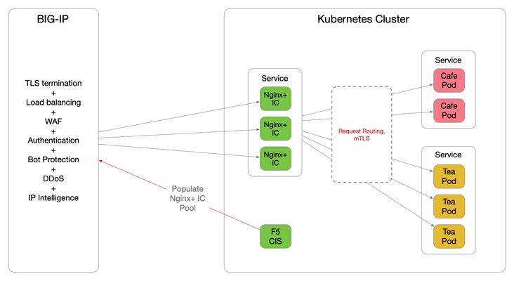
Introduction The F5 Container Ingress Services (CIS) can be integrated with the NGINX Plus Ingress Controllers (NIC) within a Kubernetes (k8s) environment. The benefits are getting the best of both worlds, with the BIG-IP providing comprehensive L4 ~ L7 security services, while leveraging NGINX Plus as the de facto standard for micro services solution. This architecture is depicted below. The integration is made fluid via the CIS, a k8s pod that listens to events in the cluster and dynamically populates the BIG-IP pool pointing to the NIC's as they scale. There are a few components need to be stitched together to support this integration, each of which is discussed in detail over the proceeding sections. NGINX Plus Ingress Controller Follow this (https://docs.nginx.com/nginx-ingress-controller/installation/building-ingress-controller-image/) to build the NIC image. The NIC can be deployed using the Manifests either as a Daemon-Set or a Service. See this ( https://docs.nginx.com/nginx-ingress-controller/installation/installation-with-manifests/ ). A sample Deployment file deploying NIC as a Service is shown below, apiVersion: apps/v1 kind: Deployment metadata: name: nginx-ingress namespace: nginx-ingress spec: replicas: 3 selector: matchLabels: app: nginx-ingress template: metadata: labels: app: nginx-ingress #annotations: #prometheus.io/scrape: "true" #prometheus.io/port: "9113" spec: serviceAccountName: nginx-ingress imagePullSecrets: - name: abgmbh.azurecr.io containers: - image: abgmbh.azurecr.io/nginx-plus-ingress:edge name: nginx-plus-ingress ports: - name: http containerPort: 80 - name: https containerPort: 443 #- name: prometheus #containerPort: 9113 securityContext: allowPrivilegeEscalation: true runAsUser: 101 #nginx capabilities: drop: - ALL add: - NET_BIND_SERVICE env: - name: POD_NAMESPACE valueFrom: fieldRef: fieldPath: metadata.namespace - name: POD_NAME valueFrom: fieldRef: fieldPath: metadata.name args: - -nginx-plus - -nginx-configmaps=$(POD_NAMESPACE)/nginx-config - -default-server-tls-secret=$(POD_NAMESPACE)/default-server-secret - -ingress-class=sock-shop #- -v=3 # Enables extensive logging. Useful for troubleshooting. #- -report-ingress-status #- -external-service=nginx-ingress #- -enable-leader-election #- -enable-prometheus-metrics Notice the ‘- -ingress-class=sock-shop’ argument, it means that the NIC will only work with an Ingress that is annotated with ‘sock-shop’. The absence of this annotation makes NIC the default for all Ingress created. Below shows the counterpart Ingress with the ‘sock-shop’ annotation. apiVersion: extensions/v1beta1 kind: Ingress metadata: name: sock-shop-ingress annotations: kubernetes.io/ingress.class: "sock-shop" spec: tls: - hosts: - socks.ab.gmbh secretName: wildcard.ab.gmbh rules: - host: socks.ab.gmbh http: paths: - path: / backend: serviceName: front-end servicePort: 80 This Ingress says if hostname is socks.ab.gmbh and path is ‘/’, send traffic to a service named ‘front-end’, which is part of the socks application itself. The above concludes Ingress configuration with the NIC. F5 Container Ingress Services The next step is to leverage the CIS to dynamically populate the BIG-IP pool with the NIC addresses. Follow this ( https://clouddocs.f5.com/containers/v2/kubernetes/kctlr-app-install.html ) to deploy the CIS. A sample Deployment file is shown below, apiVersion: extensions/v1beta1 kind: Deployment metadata: name: k8s-bigip-ctlr-deployment namespace: kube-system spec: # DO NOT INCREASE REPLICA COUNT replicas: 1 template: metadata: name: k8s-bigip-ctlr labels: app: k8s-bigip-ctlr spec: # Name of the Service Account bound to a Cluster Role with the required # permissions serviceAccountName: bigip-ctlr containers: - name: k8s-bigip-ctlr image: "f5networks/k8s-bigip-ctlr" env: - name: BIGIP_USERNAME valueFrom: secretKeyRef: # Replace with the name of the Secret containing your login # credentials name: bigip-login key: username - name: BIGIP_PASSWORD valueFrom: secretKeyRef: # Replace with the name of the Secret containing your login # credentials name: bigip-login key: password command: ["/app/bin/k8s-bigip-ctlr"] args: [ # See the k8s-bigip-ctlr documentation for information about # all config options # https://clouddocs.f5.com/products/connectors/k8s-bigip-ctlr/latest "--bigip-username=$(BIGIP_USERNAME)", "--bigip-password=$(BIGIP_PASSWORD)", "--bigip-url=https://x.x.x.x:8443", "--bigip-partition=k8s", "--pool-member-type=cluster", "--agent=as3", "--manage-ingress=false", "--insecure=true", "--as3-validation=true", "--node-poll-interval=30", "--verify-interval=30", "--log-level=INFO" ] imagePullSecrets: # Secret that gives access to a private docker registry - name: f5-docker-images # Secret containing the BIG-IP system login credentials - name: bigip-login Notice the following arguments below. They tell the CIS to consume AS3 declaration to configure the BIG-IP. According to PM, CCCL(Common Controller Core Library) – used to orchestrate F5 BIG-IP, is getting removed this sprint for the CIS 2.0 release. '--manage-ingress=false' means CIS is not doing anything for Ingress resources defined within the k8s, this is because that CIS is not the Ingress Controller, NGINX Plus is, as far as k8s is concerned. The CIS will create a partition named k8s_AS3 on the BIG-IP, this is used to hold L4~7 configuration relating to the AS3 declaration. The best practice is also to manually create a partition named 'k8s' (in our example), where networking info will be stored (e.g., ARP, FDB). "--bigip-url=https://x.x.x.x:8443", "--bigip-partition=k8s", "--pool-member-type=cluster", "--agent=as3", "--manage-ingress=false", "--insecure=true", "--as3-validation=true", To apply AS3, the declaration is embedded within a ConfigMap applied to the CIS pod. kind: ConfigMap apiVersion: v1 metadata: name: as3-template namespace: kube-system labels: f5type: virtual-server as3: "true" data: template: | { "class": "AS3", "action": "deploy", "persist": true, "declaration": { "class": "ADC", "id":"1847a369-5a25-4d1b-8cad-5740988d4423", "schemaVersion": "3.16.0", "Nginx_IC": { "class": "Tenant", "Nginx_IC_vs": { "class": "Application", "template": "https", "serviceMain": { "class": "Service_HTTPS", "virtualAddresses": [ "10.1.0.14" ], "virtualPort": 443, "redirect80": false, "serverTLS": { "bigip": "/Common/clientssl" }, "clientTLS": { "bigip": "/Common/serverssl" }, "pool": "Nginx_IC_pool" }, "Nginx_IC_pool": { "class": "Pool", "monitors": [ "https" ], "members": [ { "servicePort": 443, "shareNodes": true, "serverAddresses": [] } ] } } } } } They are telling the BIG-IP to create a tenant called ‘Nginx_IC’, a virtual named ‘Nginx_IC_vs’ and a pool named ‘Nginx_IC_pool’. The CIS will update the serverAddresses with the NIC addresses dynamically. Now, create a Service to expose the NIC’s. apiVersion: v1 kind: Service metadata: name: nginx-ingress namespace: nginx-ingress labels: cis.f5.com/as3-tenant: Nginx_IC cis.f5.com/as3-app: Nginx_IC_vs cis.f5.com/as3-pool: Nginx_IC_pool spec: type: ClusterIP ports: - port: 443 targetPort: 443 protocol: TCP name: https selector: app: nginx-ingress Notice the labels, they match with the AS3 declaration and this allows the CIS to populate the NIC’s addresses to the correct pool. Also notice the kind of the manifest ‘Service’, this means only a Service is created, not an Ingress, as far as k8s is concerned. On the BIG-IP, the following should be created. The end product is below. Please note that this article is focused solely on control plane, that is, how to get the CIS to populate the BIG-IP with NIC's addresses. The specific mechanisms to deliver packets from the BIG-IP to the NIC's on the data plane is not discussed, as it is decoupled from control plane. For data plane specifics, please take a look here ( https://clouddocs.f5.com/containers/v2/ ). Hope this article helps to lift the veil on some integration mysteries.5.1KViews11likes27Comments