snat vs automap, whats the difference?
I'm trying to see the difference between the snat and automap for the Source Address Translation option. Currently I have traffic coming in to the F5 using automap. What though specifically does that mean? And why wouldn't I use SNAT? All the nodes, (servers in our lan), are not configured to have the F5 as its default gateway. I have a lot of virtual servers configured and I'm not sure how the self-ip plays a role in the nating or snating if at all. From what I understand (but could be wrong) an external client request is directed to the vip ip (since our firewall nats it there) and the destination IP is that of the vip. The F5 then translates the destination IP to that of the IP of the pool member. Then on the way back out the source is translated to the of the vip. But what about the selfip? Can someone please explain all this? Thanks!14KViews0likes8Comments
How to preserve data in a HTTP 302 redirect of a POST
Hi, We are trying to implement the following scenario and would like to know if the LTM can do the following: An application execute an HTTP POST request with parameters inside the HTML body LTM sends back a 302 redirect request back to the client to another local url How can LTM sends back in the 302 redirect with the same parameters that were availble in the initial packet (see 1))? Can LTM look into HTML body and use them in packet 2) with an iRule? In initial packet 1) these parameters can be a small text or a large file that is being posted to the servers behind LTM Thanks, Giulio.5.5KViews0likes12Comments
Can LTM be used to configure Active and Passive Servers?
For a given vip is it possible to define pool of servers that are active and also some pool of members that passive. Basically this is what I want to do: 1. Define active pool of servers for a vip 2. Define passive pool of servers for a vip 3. When all the members in pool go down then make passive pool active Is it possible to do that in LTM? If it's possible then when one of the pool members (previously active) become active again does it switch it back?4.2KViews0likes46Comments
What exactly does FastL4 profile do?
Customer have to load balance a webserver. Using default settings it takes more than 10 seconds to completely load the webpage. After using the FastL4 profile it takes only 3 seconds. So what does it do to speed this up? We tested also the Fasthttp profile but some objects in the webpage cannot be loaded. Is there any limitation for this profile? Thanks a lot.4.2KViews0likes14Comments
Application Web Pages Not Being Served Correctly by F5
Hi, One of our customers has an application that doesn't appear to perform very well when load-balanced by the F5. The application is currently using a Standard VS profile, which is not doing SSL offload, uses cookie persistence and a SNAT pool with a single IP address and pretty much everything else is default. We have recently applied a Web Acceleration profile to the VS to attempt to address the problem but it doesn't appear to have solved anything. The WA profile is only set to cache and serve up static CSS and JS files. The major issue, we believe, is that the client fails to receive some of the Javascript that is necessary for the page to render correctly. This was the case prior to the WA profile being applied as well as after. The application used to be load-balanced, in a very rudimentary way, by iptables and these issues were not seen then. I'm very keen to find any clue as to where to look on the F5 for what could be causing the problem. I'm considering changing the profile to Perf L4 to see if it helps but there are two problems with that: 1. I don't get to learn what was causing the problem 2. I think the client wants to have the F5 do SSL offload in the near future Any help would be greatly appreciated. Thanks in advance, Ben4.1KViews0likes22CommentsRouting traffic by URI using iRule
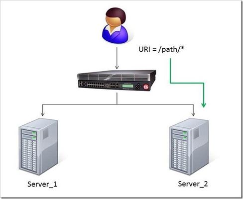
The DevCentral team recently developed a solution for routing traffic to a specific server based on the URI path. A BIG-IP Local Traffic Manager (LTM) sits between the client and two servers to load balance the traffic for those servers. The Challenge: When a user conducts a search on a website and is directed to one of the servers, the search information is cached on that server. If another user searches for that same data but the LTM load balances to the other server, the cached data from the first server does him no good. So to solve this caching problem, the customer wants traffic that contains a specific search parameter to be routed to the second server (as long as the server is available). Specifically in this case, when a user loads a page and the URI starts with /path/* that traffic should be sent to Server_2. The picture below shows a representation of what the customer wants to accomplish: The Solution: So, the question becomes: How does the customer ensure all /path/* traffic is sent to a specific server? Well, you guessed it...the ubiquitous and loveable iRule! Everyone had a pretty good idea an iRule would be used to solve this problem, but what does that iRule look like? Well, here it is!! when HTTP_REQUEST { if { [string tolower [HTTP::path]] starts_with "/path/" } { persist none set pm [lsearch -inline [active_members -list <pool name>] x.x.x.x*] catch { pool <pool name> member [lindex $pm 0] [lindex $pm 1] } } } Let's talk through the specifics of this solution... For efficiency, start by checking the least likely condition. If an HTTP_REQUEST comes in, immediately check for the "/path/" string. Keep in mind the "string tolower" command on the HTTP::path before the comparison to "/path/" to ensure the cases match correctly. Also, notice the use of HTTP::path instead of the full URI for the comparison...there's no need to use the full URI for this check. Next, turn off persistence just in case another profile or iRule is forcing the connection to persist to a place other than the beloved Server_2. Then, search all active members in the pool for the Server_2 IP address and port. The "lsearch -inline" ensures the matching value is returned instead of just the index. The "active_members -list" is used to ensure we get a list of IP addresses and ports, not just the number of active members. Note the asterisk behind the IP address in the search command...this is needed to ensure the port number is included in the search. Based on the searches, the resulting values are set in a variable called "pm". Next, use the catch command to stop any TCL errors from causing problems. Because we are getting the active members list, it's possible that the pool member we are trying to match is NOT active and therefore the pool member listed in the pool command may not be there...this is what might cause that TCL error. Then send the traffic to the correct pool member, which requires the IP and port. The astute observer and especially the one familiar with the output of "active_members -list" will notice that each pool member returned in the list is already pre-formatted in "ip port" format. However, just using the pm variable in the pool command returns a TCL error, likely because the pm variable is a single object instead of two unique objects. So, the lindex is used to pull out each element individually to avoid the TCL error. Testing: Our team tested the iRule by adding it to a development site and then accessing several pages on that site. We made sure the pages included "/path/" in the URIs! We used tcpdump on the BIG-IP to capture the transactions (tcpdump -ni 0.0 -w/var/tmp/capture1.pcap tcp port 80 -s0) and then downloaded them locally and used Wireshark for analysis. Using these tools, we determined that all the "/path/" traffic routed to Server_2 and all other traffic was still balanced between Server_1 and Server_2. So, the iRule worked correctly and it was ready for prime time! Special thanks to Jason Rahm and Joe Pruitt for their outstanding technical expertise and support in solving this challenge! For more information on this iRule or any other LTM issues, you can submit questions/comments in the "Comments" section below, or you can contact the DevCentral team at https://devcentral.f5.com/s/community/contact-us.4KViews0likes5CommentsF5 in AWS Part 1 - AWS Networking Basics
Updated for Current Versions and Documentation Part 1 : AWS Networking Basics Part 2: Running BIG-IP in an EC2 Virtual Private Cloud Part 3: Advanced Topologies and More on Highly-Available Services Part 4: Orchestrating BIG-IP Application Services with Open-Source Tools Part 5: Cloud-init, Single-NIC, and Auto Scale Out of BIG-IP in v12 If you work in IT, and you haven’t been living under a rock, then you have likely heard of Amazon Web Services (AWS). There has been a substantial increase in the maturity and stability of the AWS Elastic Compute Cloud (EC2), but you are wondering – can I continue to leverage F5 services in AWS? In this series of blog posts, we will discuss the how and why of running F5 BIG-IP in EC2. In this specific article, we’ll start with the basics of the AWS EC2 and Virtual Private Cloud (VPC). Later in the series, we will discuss some of the considerations associated with running BIG-IP as compute instance in this environment, we’ll outline the best deployment models for your application in EC2, and how these deployment models can be automated using open-source tools. Note: AWS uses the terms "public" and "private" to refer to what F5 Networks has typically referred to as "external" and "internal" respectively. We will use this terms interchangeably. First, what is AWS? If you have read the story, you will know that the EC2 project began with an internal interest at Amazon to move away from messy, multi-tenant networks using VLANs for segregation. Instead, network engineers at Amazon wanted to build an entirely IP-based architecture. This vision morphed into the universe of application services available today. Of course, building multi-tenant, purely L3 networks at massive scale had implications for both security and redundancy (we’ll get to this later). Today, EC2 enables users to run applications and services on top of virtualized network, storage, and compute infrastructure, where hosts are deployed in the form of Amazon Machine Images (AMIs). These AMIs can either be private to the user or launched from the public AWS marketplace. Hosts can be added to elastic load balancing (ELB) groups and associated with publicly accessible IPs to implement a simple horizontal model for availability. AWS became truly relevant for the enterprise with the introduction of the Virtual Private Cloud service. VPCs enabled users to build virtual private networks at the IP layer. These private networks can be connected to on-premise configurations by way of a VPN Gateway, or connected to the internet via an Internet Gateway. When deploying hosts within a VPC, the user has a significant amount of control over how each host is attached to the network. For example, a host can be attached to multiple networks and given several public or private IPs on one or multiple interfaces. Further, users can control many of the security aspects they are used to configuring in an on-premise environment (albeit in a slightly different way), including network ACLs, routing, simple firewalling, DHCP options, etc. Lets talk about these and other important EC2 aspects and try to understand how they affect our application deployment strategy. L2 Restrictions As we mentioned above, one of the design goals of AWS was to remove layer 2 networking. This is a worthy accomplishment but we lose access to certain useful protocols, including ARP (and gratuitious ARP), broadcast and multi-cast groups, 802.1Q tagging. We can no longer use VLANs for some availability models, for quality of service management, or for tenant isolation. Network Interfaces For larger topologies, one of the largest impacts given the removal of 802.1Q protocol support is the number of subnets we can attach to a node in the network. Because in AWS each interface is attached as a layer 3 endpoint, we must add an interface for each subnet. This contrasts with traditional networks, where you can add VLANs to your trunk for each subnet via tagging. Even though we're in a virtual world, the number of virtual network interfaces (or Elastic Network Interfaces (ENIs) in AWS terminology) is also limited according to the EC2 instance size. Together, the limits on number of interfaces and mapping between interface and subnet effectively limit the number of directly connected networks we can attach to a device (like BIG-IP, for example). IP Addressing AWS offers two kinds of globally routable IP address; these are “Public IP Addresses” and “Elastic IP Address”. In the table below, we outlined some of the differences between these two types of IP addresses. You can probably figure out for yourself why we will want to use Elastic IPs with BIG-IP. Like interfaces, AWS limits the number of IPs in several ways, including the number of IPs that can be attached to an interface and the number of elastic IPs per AWS account. Table 1: Differences between Public and Elastic IP Addresses Public IP Elastic IP Released on device termination/disassociation YES NO Assignable to secondary interfaces NO YES Can be associated after launch NO YES Amazon provides more information on public and elastic IP addresses here: http://docs.aws.amazon.com/AWSEC2/latest/UserGuide/using-instance-addressing.html#concepts-public-addresses Each interface on an EC2 instance is given a private IP address. This IP address is routable locally through your subnet and assigned from the address range associated with the subnet to which your interface is attached. Multiple private secondary IP addresses can be attached to an interface, and is a useful technique for creating more complex topologies. The number of interfaces and private IPs per interface within an Amazon VPC are listed here: http://docs.aws.amazon.com/AWSEC2/latest/UserGuide/using-eni.html#AvailableIpPerENI NAT Instances, Subnets and Routing When creating a VPC using the wizard available in the AWS VPC web portal, several default configurations are possible. One of these configurations is “VPC with Public and Private subnets”. In this configuration, what if the instances on our private subnet wish to access the outside world? Because we cannot attach public or elastic IP address to instances within the private subnet, we must use NAT provided by AWS. Like BIG-IP and other network devices in EC2, the NAT instance will live as a compute node within your VPC. This is good way to allow outbound traffic from your internal servers, but to prevent those servers from receiving inbound traffic. When you create subnets manually or through the VPC wizard, you’ll note that each subnet has an associated routing table. These route tables may be updated to control traffic flow between instances and subnets in your VPC. Regions and Availability Zones We know quite a few number of people who have been confused by the concept of availabilty zones in EC2. To put it clearly, an availabilty zone is a physically isolated datacenter in a region. Regions may contain mulitple availability zones. Availabilty zones run on different networking and storage infrastructure, and depend on seperate power supplies and internet connections. Striping your application deployments across availability zones is a great way to provide redundancy and, perhaps a hot standby, but please note that these are not the same thing. Amazon does not mirror any data between zones on behalf of the customer. While VPCs can span availability zones, subnets may not. To close this blog post, we are fortunate enough to get a video walk through from Vladimir Bojkovic, Solution Architect at F5 Networks. He shows how to create a VPC with internal and external subnets as a practical demonstration of the concepts we discussed above.4KViews2likes4Comments
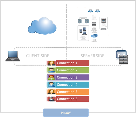
The Full-Proxy Data Center Architecture
Why a full-proxy architecture is important to both infrastructure and data centers. In the early days of load balancing and application delivery there was a lot of confusion about proxy-based architectures and in particular the definition of a full-proxy architecture. Understanding what a full-proxy is will be increasingly important as we continue to re-architect the data center to support a more mobile, virtualized infrastructure in the quest to realize IT as a Service. THE FULL-PROXY PLATFORM The reason there is a distinction made between “proxy” and “full-proxy” stems from the handling of connections as they flow through the device. All proxies sit between two entities – in the Internet age almost always “client” and “server” – and mediate connections. While all full-proxies are proxies, the converse is not true. Not all proxies are full-proxies and it is this distinction that needs to be made when making decisions that will impact the data center architecture. A full-proxy maintains two separate session tables – one on the client-side, one on the server-side. There is effectively an “air gap” isolation layer between the two internal to the proxy, one that enables focused profiles to be applied specifically to address issues peculiar to each “side” of the proxy. Clients often experience higher latency because of lower bandwidth connections while the servers are generally low latency because they’re connected via a high-speed LAN. The optimizations and acceleration techniques used on the client side are far different than those on the LAN side because the issues that give rise to performance and availability challenges are vastly different. A full-proxy, with separate connection handling on either side of the “air gap”, can address these challenges. A proxy, which may be a full-proxy but more often than not simply uses a buffer-and-stitch methodology to perform connection management, cannot optimally do so. A typical proxy buffers a connection, often through the TCP handshake process and potentially into the first few packets of application data, but then “stitches” a connection to a given server on the back-end using either layer 4 or layer 7 data, perhaps both. The connection is a single flow from end-to-end and must choose which characteristics of the connection to focus on – client or server – because it cannot simultaneously optimize for both. The second advantage of a full-proxy is its ability to perform more tasks on the data being exchanged over the connection as it is flowing through the component. Because specific action must be taken to “match up” the connection as its flowing through the full-proxy, the component can inspect, manipulate, and otherwise modify the data before sending it on its way on the server-side. This is what enables termination of SSL, enforcement of security policies, and performance-related services to be applied on a per-client, per-application basis. This capability translates to broader usage in data center architecture by enabling the implementation of an application delivery tier in which operational risk can be addressed through the enforcement of various policies. In effect, we’re created a full-proxy data center architecture in which the application delivery tier as a whole serves as the “full proxy” that mediates between the clients and the applications. THE FULL-PROXY DATA CENTER ARCHITECTURE A full-proxy data center architecture installs a digital "air gap” between the client and applications by serving as the aggregation (and conversely disaggregation) point for services. Because all communication is funneled through virtualized applications and services at the application delivery tier, it serves as a strategic point of control at which delivery policies addressing operational risk (performance, availability, security) can be enforced. A full-proxy data center architecture further has the advantage of isolating end-users from the volatility inherent in highly virtualized and dynamic environments such as cloud computing . It enables solutions such as those used to overcome limitations with virtualization technology, such as those encountered with pod-architectural constraints in VMware View deployments. Traditional access management technologies, for example, are tightly coupled to host names and IP addresses. In a highly virtualized or cloud computing environment, this constraint may spell disaster for either performance or ability to function, or both. By implementing access management in the application delivery tier – on a full-proxy device – volatility is managed through virtualization of the resources, allowing the application delivery controller to worry about details such as IP address and VLAN segments, freeing the access management solution to concern itself with determining whether this user on this device from that location is allowed to access a given resource. Basically, we’re taking the concept of a full-proxy and expanded it outward to the architecture. Inserting an “application delivery tier” allows for an agile, flexible architecture more supportive of the rapid changes today’s IT organizations must deal with. Such a tier also provides an effective means to combat modern attacks. Because of its ability to isolate applications, services, and even infrastructure resources, an application delivery tier improves an organizations’ capability to withstand the onslaught of a concerted DDoS attack. The magnitude of difference between the connection capacity of an application delivery controller and most infrastructure (and all servers) gives the entire architecture a higher resiliency in the face of overwhelming connections. This ensures better availability and, when coupled with virtual infrastructure that can scale on-demand when necessary, can also maintain performance levels required by business concerns. A full-proxy data center architecture is an invaluable asset to IT organizations in meeting the challenges of volatility both inside and outside the data center. Related blogs & articles: The Concise Guide to Proxies At the Intersection of Cloud and Control… Cloud Computing and the Truth About SLAs IT Services: Creating Commodities out of Complexity What is a Strategic Point of Control Anyway? The Battle of Economy of Scale versus Control and Flexibility F5 Friday: When Firewalls Fail… F5 Friday: Platform versus Product3.9KViews1like1Comment